


Commer
Commer
Commer
Commer
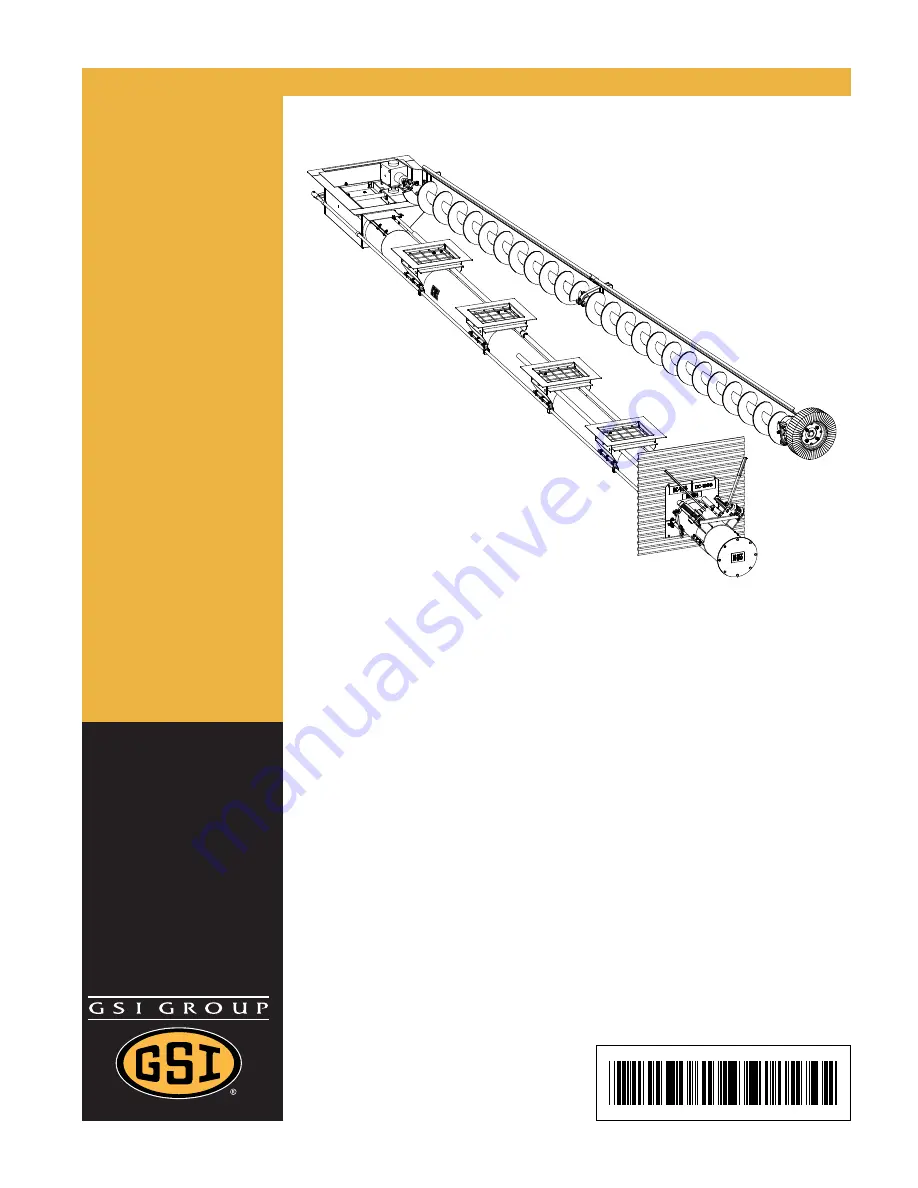
Commercial
cial
cial
cial
cial
Dir
Dir
Dir
Dir
Direct Gear Dri
ect Gear Dri
ect Gear Dri
ect Gear Dri
ect Gear Drivvvvve
ee
ee
Bin Sw
Bin Sw
Bin Sw
Bin Sw
Bin Swee
ee
ee
ee
eep
p
p
p
p A
A
A
A
Aug
ug
ug
ug
uger
er
er
er
er
Assemb
Assemb
Assemb
Assemb
Assembllllly &
y &
y &
y &
y &
Oper
Oper
Oper
Oper
Opera
aa
aation Man
tion Man
tion Man
tion Man
tion Manual
ual
ual
ual
ual
PNEG
PNEG
PNEG
PNEG
PNEG-1521
-1521
-1521
-1521
-1521
Date: 08-19-10
Date: 08-19-10
Date: 08-19-10
Date: 08-19-10
Date: 08-19-10
PNEG-1521


