Grouser Products 760, Owner'S Manual & Parts Book
Introducing the Philips 760 - a versatile and innovative electronic device that enhances your everyday life. Accessing the product's user manual is quick and easy. Download it for free from our website and unleash the full potential of your Philips 760 to make the most of its incredible features and capabilities.
Share
Download


Reviews:
No comments
Related manuals for 760

HS Series
Brand: cam Pages: 28

EXCEL
Brand: ICC Pages: 32

Horus
Brand: GCE Pages: 16

Elite XL-1208
Brand: GCC Technologies Pages: 12

2591
Brand: Wagan Pages: 12

SideWinder
Brand: Yakima Pages: 8

SH003B
Brand: SimplyHome Pages: 2

DBK2
Brand: OBO Bettermann Pages: 2

SR16220
Brand: Swann Pages: 12

WS-6926
Brand: Satlink Pages: 16

RBS 2106
Brand: Ericsson Pages: 487

Ocean Seven 304Plus
Brand: idronaut Pages: 79

UNIVERSAL 1050
Brand: Jetmaster Pages: 13

T113 FABRIZIO
Brand: Spector&Co Pages: 9

Analog signal conditioner AD-4541-V
Brand: A&D Pages: 1

Micropulse BTL5 Series
Brand: Balluff Pages: 94

QF018
Brand: Qusun Electric Pages: 6
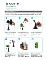
AA-05
Brand: Bauhn Pages: 2


