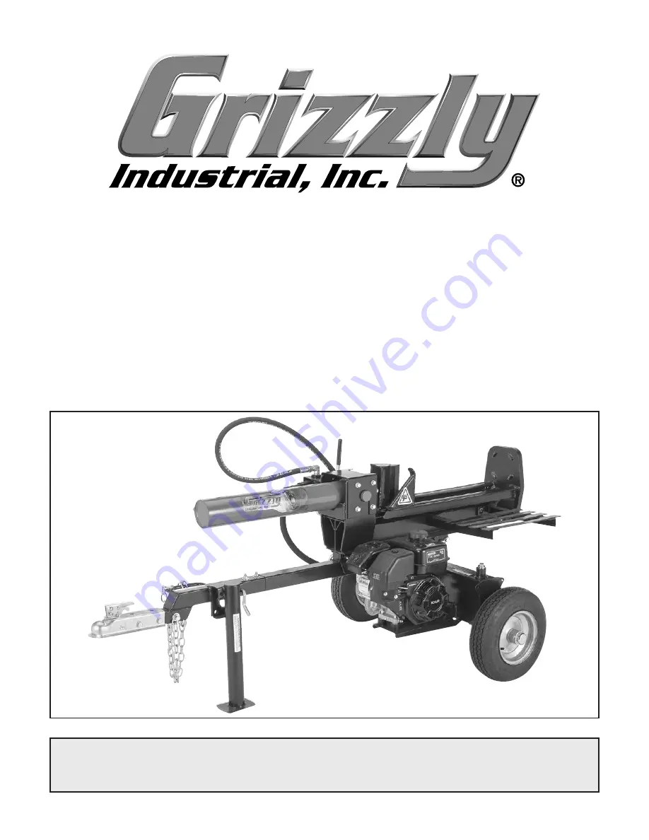
background image

MODEL T27710

22-TON LOG SPLITTER

w/KOHLER ENGINE

OWNER'S MANUAL

(For models manufactured since 04/16)

COPYRIGHT © JUNE, 2016 BY GRIZZLY INDUSTRIAL, INC.


WARNING: NO PORTION OF THIS MANUAL MAY BE REPRODUCED IN ANY SHAPE

 OR FORM WITHOUT THE WRITTEN APPROVAL OF GRIZZLY INDUSTRIAL, INC.

#BLWK18211  PRINTED IN CHINA

V1.06.16

Summary of Contents for T27710

Page 1: ...S MANUAL For models manufactured since 04 16 COPYRIGHT JUNE 2016 BY GRIZZLY INDUSTRIAL INC WARNING NO PORTION OF THIS MANUAL MAY BE REPRODUCED IN ANY SHAPE OR FORM WITHOUT THE WRITTEN APPROVAL OF GRIZ...

Page 2: ...g grinding tool integrity and the usage of personal protective equipment The manufacturer will not be held liable for injury or property damage from negligence improper training machine modifications...

Page 3: ...9 SECTION 3 OPERATIONS 21 Operation Overview 21 Job Site Considerations 22 Transporting 22 Control Lever 23 Splitting Logs 24 Removing Stuck Logs 25 SECTION 4 ACCESSORIES 26 SECTION 5 MAINTENANCE 28 S...

Page 4: ...ade every effort to be exact with the instruc tions specifications drawings and photographs in this manual Sometimes we make mistakes but our policy of continuous improvement also means that sometimes...

Page 5: ...n this manual A 2 Tow Bar Coupler B Coupler Lock Lever C Hydraulic Tank Filter D Beam Lock Pin E Hydraulic Pump F Control Lever G Hydraulic Cylinder Assembly H Splitting Wedge I Dislodger J Beam K Foo...

Page 6: ...draulic Tank Filter Removes contami nants from hydraulic fluid flowing back to hydraulic tank To reduce your risk of serious injury read this entire manual BEFORE using machine Refer to Figures 1 4 an...

Page 7: ...Lever Controls choke valve and air to fuel ratio in engine Move lever left to ON I position when starting engine when it is cold Move lever right to OFF position O after engine starts Use this positi...

Page 8: ...ement 196 CC Oil Capacity 0 63 qt Hydraulic Information Hydraulic Cylinder Size Diameter x Length 4 x 23 in Automatic Cylinder Return Yes Maximum Pump Pressure 3600 PSI Pump Rating 11 GPM 2 Stage Hydr...

Page 9: ...Wheel Bearing Type Tapered Roller Jackstand Included Yes Other Specifications Country of Origin China Warranty 1 Year Serial Number Location ID Label ISO 9001 Factory Yes Certified by a Nationally Re...

Page 10: ...oof DANGEROUS ENVIRONMENTS Do not use machinery in areas that are wet cluttered or have poor lighting Operating machinery in these areas greatly increases the risk of accidents and injury MENTAL ALERT...

Page 11: ...moving parts or flying debris Make sure they are properly installed undamaged and working correctly BEFORE operating machine FORCING MACHINERY Do not force machine It will do the job safer and better...

Page 12: ...ssure relief valve hydraulic lines and increase risk of operator injury CORRECT USAGE Never attempt to split more than one log at a time Doing so may cause logs to fly off splitter with great force re...

Page 13: ...til you are completely satisfied with the machine and have resolved any issues between Grizzly or the shipping agent You MUST have the original pack aging to file a freight claim It is also extremely...

Page 14: ...e g a nut or a washer we will gladly replace them or for the sake of expediency replacements can be obtained at your local hardware store Box Inventory Figures 5 6 Qty A Wheel Assemblies 2 B Support L...

Page 15: ...mm Cylinder Beam 1 T Hairpin Cotter Pin 13 4 x 21 2 Cylinder Beam 1 U Fender Washers 10mm Engine 4 V Rubber Spacers Engine 4 W Hex Bolts M8 1 25 x 65 Engine 4 X Fender Washers 8mm Engine 4 Y Lock Wash...

Page 16: ...ive humidity range is outside 20 95 non condensing or the environment is subject to vibration shocks or bumps Children or untrained people may be seriously injured by this machine Only install in an a...

Page 17: ...em Slotted Hex Nut Figure 10 Installing wheel onto axle 3 Bend both cotter pin tangs so wheel is held onto axle and tap axle cap see Figure 10 onto wheel 5 Pull lock pin out and pivot support leg unti...

Page 18: ...c cylinder and beam to frame tube 9 Re install cylinder cover with 8 M10 1 5 x 20 hex bolts 8 10mm lock washers and 8 10mm flat washers that were removed in Step 8 see Figure 15 10 With help of assist...

Page 19: ...h pressure hose onto pump pressure fitting see Figure 22 with 1 11 2 x 2 4 O ring Figure 22 High pressure hose and control lever Pump Pressure Fitting High Pressure Hose Figure 21 Pump pressure port L...

Page 20: ...return hose onto tank hydraulic filter fitting see Figure 23 making sure O ring stays in place Note Tighten hydraulic hose connector to 18 20 inch pounds Figure 24 Engine gas cap and oil fill plug lo...

Page 21: ...u al to become familiar with controls and operations before starting engine and using log splitter HYDRAULIC INJECTION HAZARD Hydraulic fluid leaks can be under sufficient pressure to penetrate your s...

Page 22: ...ion change engine oil refer to Kohler engine manual for details 6 Pull starter handle see Figure 28 slow ly until resistance is felt Retract handle then pull handle quickly with smooth steady motion u...

Page 23: ...easier to understand Due to the generic nature of this overview it is not intended to be an instructional guide To learn more about specific operations read this entire manual and seek additional tra...

Page 24: ...to move logs to and from the splitter Keep your work zone clear of lumber to avoid trip ping hazards while using the machine To tow splitter 1 Lower log splitter cylinder and beam to hori zontal posit...

Page 25: ...le fire Figure 35 Fuel shutoff valve and gas cap location Fuel Shutoff Valve Gas Cap 8 Make sure engine gas cap see Figure 35 is secure and there are no tools or logs still on log splitter Never allow...

Page 26: ...erely injure or kill bystanders or yourself The log splitter can be operated in either the hori zontal or vertical position as shown in Figure 37 The horizontal position is generally for lighter easy...

Page 27: ...Best placement of log against beam and foot plate horizontal operation shown Never use your hands to remove a log stuck on wedge as it could crush hands and fin gers during accidental startup Always u...

Page 28: ...zly offers a wide selection of synthetic and leather gloves for all day comfort in a variety of working conditions Figure 41 Assortment of gloves T21272 T21273 T20692 Basic Eye Protection T20451 Kirov...

Page 29: ...ar panel for easy loading and unloading and a maximum capacity of 500 lbs Dimensions 59 L x 301 2 W x 231 2 H Figure 43 T10028 Pair of Wheel Chocks Figure 45 T27709 Dump Cart H7824 2 Stainless Ball Hi...

Page 30: ...bricate wheel bushings on this page As Needed Inspect for burnt smelling or tan colored water contaminated hydraulic fluid If con taminated replace tank vented cap clean tank filter strainer flush sys...

Page 31: ...and carefully remove plug from bottom of hydraulic tank Allow fluid to drain to bring it to correct level Re install drain plug when finished 5 Re install vented cap 6 Start engine Use control lever t...

Page 32: ...nstall suction filter rubber gasket and hose 12 Fill tank with 3 5 gallons of hydraulic fluid and re install tank vented cap 13 Check hydraulic fluid level refer to Page 29 IMPORTANT Be sure to dispos...

Page 33: ...the hydraulic tank remove the old filter and install the new one Be sure to follow any additional instructions the replacement filter manufacturer provides 1 Follow Kohler engine manual instructions f...

Page 34: ...at if you try to keep the wedge sharpened to a razor point like an axe blade you will greatly reduce the life of the wedge by always sharpening it However if you allow the point to become very dull or...

Page 35: ...inkage at fault 2 Splitting wedge dull log unsuitable for splitting 3 Hydraulic fluid too low or contaminated 4 Hydraulic control valve at fault 5 Damaged ram piston seals 1 Replace repair bent or wor...

Page 36: ...tem Figure 53 Hydraulic system components Before servicing hydraulic parts stop engine and depressurize entire hydraulic system by moving control lever back and forth a few times Ignoring this warning...

Page 37: ...8 44 44 36 33 41 39 40 33 20 55 18 5 20 70 22 62 5 20 25 53 31 59 63 64 57 37 11 66 38 57 37 69 67 38 57 60 68 65 32 61 75 12 58 B B A A 19 73 22 74 20 25 Main SECTION 8 PARTS We do our best to stock...

Page 38: ...10 17 PT27710017 HYDRAULIC TUBE 16 OD X 560 L SS 55 PT27710055 SUPPORT LEG 18 PT27710018 SAFETY PIN 56 PT27710056 EXT RETAINING RING 62MM 19 PT27710019 COMPRESSION SPRING 1 5 X 18 X 60 57 PT27710057 L...

Page 39: ...than 45 MPH 12 Tie back long hair and clothing and remove all jewelry or other loose apparel to avoid entanglement 13 Do not operate under influence of drugs or alcohol or if tired 14 Prevent unautho...

Page 40: ...38 Model T27710 Mfd Since 04 16...

Page 41: ...metalworker ____ 0 2 Years ____ 2 8 Years ____ 8 20 Years ____20 Years 6 How many of your machines or tools are Grizzly ____ 0 2 ____ 3 5 ____ 6 9 ____10 7 Do you think your machine represents a good...

Page 42: ...LINE FOLD ALONG DOTTED LINE GRIZZLY INDUSTRIAL INC P O BOX 2069 BELLINGHAM WA 98227 2069 Place Stamp Here Name_______________________________ Street_______________________________ City______________S...

Page 43: ...shall be tried in the State of Washington County of Whatcom We shall in no event be liable for death injuries to persons or property or for incidental contingent special or consequential damages arisi...

Page 44: ......

Page 45: ......

Page 46: ......

Page 47: ......

Page 48: ......

Page 49: ......

Page 50: ......

Page 51: ......

Page 52: ......

Page 53: ......

Page 54: ......

Page 55: ......

Page 56: ......

Page 57: ......

Page 58: ......

Page 59: ......

Page 60: ......

Page 61: ......

Page 62: ......

Page 63: ...24 Governor System 25 Lubrication System 26 Electrical System 30 Starter System 33 Disassembly Inspection and Service 43 Reassembly IMPORTANT Read all safety precautions and instructions carefully bef...

Page 64: ...ING Accidental Starts can cause severe injury or death Disconnect and ground spark plug lead s before servicing Before working on engine or equipment disable engine as follows 1 Disconnect spark plug...

Page 65: ...s or Annually Clean low profile air cleaner element Air Cleaner Intake Replace dual element air cleaner element Air Cleaner Intake Change oil Lubrication System Clean cooling areas Air Cleaner Intake...

Page 66: ...proved and should NOT be used effects of old stale or contaminated fuel are not warrantable Fuel must meet these requirements Clean fresh unleaded gasoline Octane rating of 87 R M 2 or higher Research...

Page 67: ...6H 15 00 0 591 SAE A FLANGE 4X 5 16 24 UNF 2B 15 00 0 591 162 00 6 378 342 20 13 473 65 05 2 561 32 53 1 281 66 00 2 598 32 53 1 281 65 05 2 561 318 66 12 545 STRAIGHT PTO 181 60 7 150 SPARK PLUG OIL...

Page 68: ...N m 70 8 in lb Blower Housing and Sheet Metal M6 Shoulder Screw 10 N m 88 5 in lb M6 Nut 8 N m 70 8 in lb Carburetor Stud 10 N m 88 5 in lb Primary Nut 8 N m 70 8 in lb Secondary Nut 10 N m 88 5 in lb...

Page 69: ...8 N m 70 8 in lb Module Screw 10 N m 88 5 in lb Oil Sentry Module Screw 8 N m 70 8 in lb Muffler M8 Exhaust Screw 24 N m 212 in lb M6 Muffler Shield Screw 8 N m 70 8 in lb M4 Muffler Shield Screw 2 N...

Page 70: ...aft End Play free 0 025 0 703 mm 0 0010 0 028 in Ball Bearing 0 003 0 25 mm 0 0001 0 0010 in Bore in crankcase New without Main Bearing 51 961 51 991 mm 2 0457 2 0469 in Bore in closure plate New with...

Page 71: ...to Piston Pin Running Clearance 0 009 0 016 mm 0 0003 0 0006 in Piston Pin Bore I D New Max Wear Limit 18 004 18 005 mm 0 7088 0 7089 in 18 05 mm 0 7106 in Piston Pin O D New Max Wear Limit 17 992 17...

Page 72: ...32 mm 0 2094 in Exhaust Valve Stem O D New Max Wear Limit 5 47 mm 0 2153 in 5 305 mm 0 2088 in Intake Valve Stem to Guide New Max Wear Limit 0 024 0 039 mm 0 001 0 002 in 0 10 mm 0 0004 in Exhaust Val...

Page 73: ...English Fastener Torque Recommendations for Standard Applications Bolts Screws Nuts and Fasteners Assembled Into Cast Iron or Steel Grade 2 or 5 Fasteners Into Aluminum Size Grade 2 Grade 5 Grade 8 Ti...

Page 74: ...logy Inc DTI 731 03 Dealer Tool Kit Domestic Complete kit of Kohler required tools Components of 25 761 39 S Ignition System Tester Cylinder Leakdown Tester Oil Pressure Test Kit Rectifier Regulator T...

Page 75: ...d brushes Individual component available Starter Brush Holding Tool Solenoid Shift SE Tools KLR 82411 SE Tools KLR 82416 Triad OHC Timing Tool Set For holding cam gears and crankshaft in timed positio...

Page 76: ...ing gear teeth Bosses will lock tool and flywheel in position for loosening tightening or removing with a puller A spanner wrench to lift rocker arms or turn crankshaft may be made out of an old junk...

Page 77: ...e to check simple causes which at first may seem too obvious to be considered For example a starting problem could be caused by an empty fuel tank Some general common causes of engine troubles are lis...

Page 78: ...indications of improper fit and seal Check air cleaner element Look for holes tears cracked or damaged sealing surfaces or other damage that could allow unfiltered air into engine A dirty or clogged e...

Page 79: ...s closed 2 Start engine and run no load high speed 3 Open clamp and note water level in tube Level in engine side should be a minimum of 10 2 cm 4 in above level in open side If level in engine side i...

Page 80: ...t Install a 3 8 in breaker bar into hole slot of holding tool so it is perpendicular to both holding tool and crankshaft PTO If flywheel end is more accessible use a breaker bar and socket on flywheel...

Page 81: ...Element 1 Remove wing nut if equipped and paper element with precleaner 2 Separate precleaner from element service precleaner and replace element 3 Reinstall precleaner over paper element secure with...

Page 82: ...k to carburetor 1 Stop engine 2 Turn fuel shut off lever to OFF position 3 Remove fuel shut off cup 4 Clean fuel shut off cup with solvent and wipe dry 5 Inspect for worn or damaged O ring replace as...

Page 83: ...uretor 1 Make sure fuel tank is filled with clean fresh gasoline 2 Make sure fuel tank cap vent is not blocked and is operating properly 3 Make sure fuel is reaching carburetor This includes checking...

Page 84: ...s drawn through slow air bleed jets fuel is drawn through main jet and further metered through slow jet Air and fuel are mixed in body of slow jet and exit to idle progression transfer port chamber Fr...

Page 85: ...red 5 Carefully remove main jet from carburetor After main jet is removed main nozzles can be removed through bottom of main towers Note orientation direction of nozzles End with 2 raised shoulders sh...

Page 86: ...er clockwise until it stops 5 Rotate governor shaft clockwise until it stops 6 Hold both in this position and torque governor lever nut to 10 N m 88 5 in lb Governed speed setting is determined by pos...

Page 87: ...ANGE OIL Change oil while engine is warm 1 Clean area around oil fill plug dipstick and drain plug 2 Remove drain plug and oil fill plug dipstick Drain oil completely 3 Reinstall drain plug Torque 18...

Page 88: ...e feeler gauge Adjust gap to 0 76 mm 0 03 in 2 Install plug into cylinder head 3 Torque plug to 27 N m 20 ft lb Inspection Inspect each spark plug as it is removed from cylinder head Deposits on tip a...

Page 89: ...minal J Spark Plug Boot These engines are equipped with a dependable magneto breakerless ignition In such a system electrical energy is generated by cutting of magnetic flux lines generated from ignit...

Page 90: ...resistance from small spade terminal to core of spark plug lead wire If resistance is not in this range replace module Resistance Chart Ignition Module 13 5 18 0 K ohms Cap 4 6 K ohms Spade Terminal t...

Page 91: ...y connections Connect ohmmeter leads to switch leads and check for continuity in both switch positions Condition Conclusion Continuity should be indicated when and only when switch is in OFF position...

Page 92: ...ly Battery Check specific gravity of battery If low recharge or replace battery as necessary Wiring Check for corroded connections poor ground connection Transmission or Engine Make sure clutch or tra...

Page 93: ...e it from starter for testing a Set an ohmmeter on Rx1 scale and zero meter Connect one ohmmeter lead to terminal of blue lead from relay Connect other ohmmeter lead to relay mounting bracket Conditio...

Page 94: ...ley counterclockwise until rope hole in pulley is aligned with rope guide bushing of starter housing 9 Insert unknotted end of new rope through rope hole in starter pulley and rope guide bushing of ho...

Page 95: ...cidental Starts can cause severe injury or death Disconnect and ground spark plug lead s before servicing 18 690 01 Rev C KohlerEngines com External Engine Components D J E F G I C A H B K A Oil Drain...

Page 96: ...e time for oil to drain from crankcase Remove Muffler and Heat Shield Assembly 1 Remove nuts lock washers and flat washers 2 Remove muffler assembly from exhaust outlet 3 Remove exhaust gasket from ex...

Page 97: ...r sparks from ignition Never use gasoline as a cleaning agent Remove air cleaner gasket and slide carburetor off mounting studs while disconnecting throttle linkage and dampening spring Remove carbure...

Page 98: ...eal hold block of wood against 1 flat surface of valve cover Strike wood firnly with mallet If seal doesn t break loose after 1 or 2 attempts repeat procedure on other side 1 Remove screws and remove...

Page 99: ...mm 2 4409 in 0 0059 in Valve Length Maximum 64 15 mm 2 5256 in 62 15 mm 2 4468 in Valve Length Service Limit 64 15 mm 2 5256 in 62 15 mm 2 4468 in D Face Seat Width Maximum 2 0 mm 0 079 in 2 0 mm 0 07...

Page 100: ...If cracked or badly warped cylinder head should be replaced Recondition valve seat inserts following instructions provided with valve seat cutter being used Cutting proper valve face angle as specifie...

Page 101: ...or Cross Shaft T Crankcase Bearing U Crankcase Oil Seal V Dowel Pin Remove Closure Plate NOTE Do not pry on gasket surface of crankcase or closure plate as this can cause damage and leakage 1 Remove s...

Page 102: ...ess fuel is blown out opened exhaust valve and does not hamper starting 5 Engines with ACR start much faster in cold weather than engines without ACR 6 Engines with ACR can be started with spark plugs...

Page 103: ...to ring side clearance Compare clearance to Clearance Specifications If side clearance is greater than specified a new piston must be used Measuring Piston to Bore Clearance Piston Detail A A 15 mm 0...

Page 104: ...l Sentry System 1 Remove nut securing Oil Sentry lead wire grommet assembly to crankcase 2 Pull grommet assembly from crankcase on inside 3 Remove screws securing Oil Sentry float switch to crankcase...

Page 105: ...rbor press to make sure bearings are installed straight into their respective bore until fully seated 3 Using an appropriate seal driver install oil seal into closure plate to a depth of 5 5 mm 0 217...

Page 106: ...ol ring assembly first middle compression ring second and top compression ring last Oil control ring assembly is a three piece design and consists of a top rail expander ring and bottom rail 1 Install...

Page 107: ...installed properly 1 Install woodruff key into keyway of crankshaft Be sure that key is properly seated and parallel with taper of shaft 2 Install flywheel onto crankshaft being careful not to shift p...

Page 108: ...ker Arms NOTE Push rods should always be installed in original location 1 Install push rod guide plate aligning holes for rocker arm studs Install rocker arm studs and torque to 13 6 N m 120 in lb 2 D...

Page 109: ...l a new valve cover gasket followed by valve cover on head with screws and torque to 8 0 N m 71 in lb using sequence shown Valve Cover with RTV A A RTV Sealant NOTE Always use fresh sealant Using outd...

Page 110: ...k E Dampening Spring F Control Assembly G Carburetor H Retractable Starter I On Off Wiring Harness Bullet Connector J Blower Housing K Oil Sentry Wiring Harness Bullet Connector L Oil Sentry Module M...

Page 111: ...pe handle to engage pawls and center starter to drive cup Hold in this position and torque screws to 5 4 N m 47 8 in lb External Engine Components D J E F G I C A H B K A Oil Drain Plug B Oil Fill Plu...

Page 112: ...e lever to throttle plate Install tabbed washer with tab engaged in slot and secure with nut 3 Torque nut to 5 4 N m 47 8 in lb 4 Install governor lever onto shaft 5 Connect dampening spring and throt...

Page 113: ...1 18 Spring Color Hole Spring Color Hole Spring Color Hole Spring Color Hole Spring Color Hole Spring Color Hole Spring Color Hole 3750 3950 None B 3100 3300 Gold C 3500 3700 Green A 3750 3950 Green B...

Page 114: ...recleaner onto air cleaner stud and secure with washer and wing nut if equipped 3 Install air cleaner cover and secure with wing nut Low Profile 1 Install air cleaner base and secure with screws 2 Ins...

Page 115: ...53 18 690 01 Rev C KohlerEngines com...

Page 116: ...54 KohlerEngines com 18 690 01 Rev C...

Page 117: ...55 18 690 01 Rev C KohlerEngines com...

Page 118: ...56 KohlerEngines com 18 690 01 Rev C 2015 by Kohler Co All rights reserved...

Reviews: