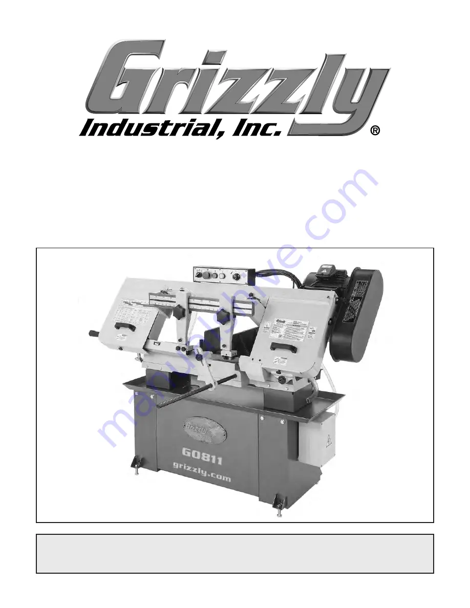
background image

MODEL G0811

9" X 16" METAL-CUTTING BANDSAW

OWNER'S MANUAL

(For models manufactured since 02/16)

COPYRIGHT © NOVEMBER, 2016 BY GRIZZLY INDUSTRIAL, INC.


WARNING: NO PORTION OF THIS MANUAL MAY BE REPRODUCED IN ANY SHAPE

 OR FORM WITHOUT THE WRITTEN APPROVAL OF GRIZZLY INDUSTRIAL, INC.

#BL18346  PRINTED IN TAIWAN

V1.02.17

Summary of Contents for G0811

Page 1: ...NUAL For models manufactured since 02 16 COPYRIGHT NOVEMBER 2016 BY GRIZZLY INDUSTRIAL INC WARNING NO PORTION OF THIS MANUAL MAY BE REPRODUCED IN ANY SHAPE OR FORM WITHOUT THE WRITTEN APPROVAL OF GRIZZLY INDUSTRIAL INC BL18346 PRINTED IN TAIWAN V1 02 17 ...

Page 2: ...ng grinding tool integrity and the usage of personal protective equipment The manufacturer will not be held liable for injury or property damage from negligence improper training machine modifications or misuse Some dust created by power sanding sawing grinding drilling and other construction activities contains chemicals known to the State of California to cause cancer birth defects or other repr...

Page 3: ...g Blade 27 Blade Breakage 28 Blade Care Break In 28 Blade Speed 29 Blade Speed Chart 30 Chip Inspection Chart 31 Feed Rate 32 Work Stop 32 Vise 33 Blade Guide Arms 35 Coolant 35 Coolant System 36 Operation Tips 37 SECTION 5 ACCESSORIES 38 SECTION 6 MAINTENANCE 41 Schedule 41 Cleaning Protecting 41 Lubrication 41 Inspecting V Belt 43 Coolant System Service 44 Machine Storage 45 SECTION 7 SERVICE 46...

Page 4: ...ade every effort to be exact with the instruc tions specifications drawings and photographs in this manual Sometimes we make mistakes but our policy of continuous improvement also means that sometimes the machine you receive is slightly different than shown in the manual If you find this to be the case and the difference between the manual and machine leaves you confused or unsure about something ...

Page 5: ...d features shown below to better understand the instructions in this manual Vise Handwheel Fixed Vise Work Stop Rod Blade Guide Scale Left Blade Guide Arm Right Blade Guide Arm Wheel Cover Blade Tension Knob Coolant Tank Blade Guide Knob Front View Rear View Headstock Movable Vise Control Panel Coolant Valve Coolant Valve Work Stop Electrical Box Blade Tension Gauge Lift Handle Pulley Cover ...

Page 6: ...rs into workpiece range is from 0 slowest to 9 fastest Turning the dial all the way clockwise locks the headstock in position Headstock Figure 2 Headstock controls and components F Blade Tension Knob and Gauge Not Shown Rotate clockwise to increase or counterclockwise to decrease blade tension Gauge indicates proper tension setting G Blade Guide Scale Displays position of blade guide arms relative...

Page 7: ...ns Type Wood Crate Content Machine Weight 690 lbs Length x Width x Height 67 x 25 x 50 in Must Ship Upright Yes Electrical Power Requirement 220V Single Phase 60 Hz Full Load Current Rating 11 8A Minimum Circuit Size 15A Connection Type Cord Plug Power Cord Included Yes Power Cord Length 6 1 2 ft Power Cord Gauge 14 AWG Plug Included Yes Recommended Plug Type 6 15 Switch Type Magnetic Switch Motor...

Page 8: ... 9 1 2 in Max Capacity Round at 45 Deg 9 in Construction Table Precision Ground Cast Iron Trunnions Cast Iron Upper Wheel Cast Iron Lower Wheel Cast Iron Body Steel Stand Steel Wheel Cover Steel Paint Type Finish Epoxy Other Wheel Size 11 3 4 in Blade Guides Upper Carbide Steel Blade Guides Lower Carbide Steel Table Info Table Size Length 31 in Table Size Width 6 1 2 in Table Size Thickness 4 1 2 ...

Page 9: ...oof DANGEROUS ENVIRONMENTS Do not use machinery in areas that are wet cluttered or have poor lighting Operating machinery in these areas greatly increases the risk of accidents and injury MENTAL ALERTNESS REQUIRED Full mental alertness is required for safe operation of machin ery Never operate under the influence of drugs or alcohol when tired or when distracted For Your Own Safety Read Instructio...

Page 10: ... moving parts or flying debris Make sure they are properly installed undamaged and working correctly BEFORE operating machine FORCING MACHINERY Do not force machine It will do the job safer and better at the rate for which it was designed NEVER STAND ON MACHINE Serious injury may occur if machine is tipped or if the cutting tool is unintentionally contacted STABLE MACHINE Unexpected movement dur i...

Page 11: ...lways follow manufacturer s cutting fluid safety instructions Pay particular attention to contact contamination inhalation storage and disposal warnings Spilled cutting fluid invites slip ping hazards HOT SURFACES Contact with hot surfaces from machine components ejections of hot chips swarf and the workpiece itself can cause burns BLADE CONDITION Do not operate with dull cracked or badly worn bla...

Page 12: ...g or fire may result especially if connected to an undersized circuit To reduce the risk of these hazards avoid over loading the machine during operation and make sure it is connected to a power supply circuit that meets the specified circuit requirements For your own safety and protection of property consult an electrician if you are unsure about wiring practices or electrical codes in your area ...

Page 13: ... extension cord used with this machine must be in good condition and contain a ground wire and matching plug receptacle Additionally it must meet the following size requirements Minimum Gauge Size 14 AWG Maximum Length Shorter is Better 50 ft Figure 4 Typical 6 15 plug and receptacle Grounding Prong Current Carrying Prongs 6 15 PLUG GROUNDED 6 15 RECEPTACLE Grounding Requirements This machine MUST...

Page 14: ...resolved any issues between Grizzly or the shipping agent You MUST have the original pack aging to file a freight claim It is also extremely helpful if you need to return your machine later Unpacking SUFFOCATION HAZARD Keep children and pets away from plastic bags or packing materials shipped with this machine Discard immediately This machine presents serious injury hazards to untrained users Read...

Page 15: ...Model G0811 Mfd Since 02 16 13 Hardware Recognition Chart USE THIS CHART TO MATCH UP HARDWARE DURING THE INVENTORY AND ASSEMBLY PROCESS 5mm 5mm Flat Head Cap Screw ...

Page 16: ...Stop 1 G Pulley Cover Knob M6 1 4 Fasteners see Hardware Recognition Chart Hex Bolts M12 1 75 x 50 Frame 4 Hex Nuts M12 1 75 Frame 8 Hex Bolts M6 1 x 12 Control Panel 2 Flat Washers 6mm Control Panel 2 Hex Nuts M8 1 25 Motor 4 Flat Washers 8mm Motor 4 Lock Washers 8mm Motor 4 Button Head Cap Screw M6 1 x 10 Pulley Cover 1 Hex Bolts M8 1 25 x 20 Pulley Cover 2 Flat Washers 8mm Pulley Cover 2 NOTICE...

Page 17: ...per optional Basic steps for removing rust preventative 1 Put on safety glasses 2 Coat the rust preventative with a liberal amount of cleaner degreaser then let it soak for 5 10 minutes 3 Wipe off the surfaces If your cleaner degreas er is effective the rust preventative will wipe off easily If you have a plastic paint scraper scrape off as much as you can first then wipe off the rest with the rag...

Page 18: ...vice described in this manual See below for required space allocation Physical Environment The physical environment where the machine is operated is important for safe operation and lon gevity of machine components For best results operate this machine in a dry environment that is free from excessive moisture hazardous chemi cals airborne abrasives or extreme conditions Extreme conditions for this...

Page 19: ...e Figure 8 Lifting machine with forklift and lifting slings 5 With an assistant helping to stabilize the load lift machine just high enough to clear pallet and any floor obstacles then place machine in final position on shop floor Power Lifting Equipment Front Lifting Strap Round Steel Bar In Lifting Holes Rear Lifting Strap 6 Thread 1 M12 1 75 hex nut onto each of 4 M12 1 75 x 50 leveling hex bol...

Page 20: ...needed However anytime local codes apply you MUST follow the anchoring methodology specified by the code Machine Base Concrete Lag Screw Lag Shield Anchor Flat Washer Drilled Hole Figure 10 Popular method for anchoring machinery to a concrete floor Anchoring to Concrete Floors Number of Mounting Holes 4 Diameter of Mounting Hardware 3 8 Assembly The machine must be fully assembled before it can be...

Page 21: ...with moderate pressure see Figure 15 Refer to Blade Speed on Page 29 to position V belt for specific blade speeds 5 Loosen knurled belt tension knob see Figure 14 until motor lowers no farther then roll V belt onto pulleys Figure 14 Belt tension knob location Belt Tension Knob Pulley Deflection Pulley Figure 15 Example of checking belt tension 1 4 Figure 16 Pulley cover secured with knob Knob 7 Cl...

Page 22: ...ious injury or death can result from using this machine BEFORE understanding its controls and related safety information DO NOT operate or allow others to operate machine until the information is understood The test run consists of verifying the following 1 the main motor runs correctly 2 the Emergency Stop button safety feature works correctly 3 the coolant pump motor runs correctly and 4 the dow...

Page 23: ...t immediately turn it OFF and disconnect power Safety feature of Emergency Stop button is NOT working properly and must be replaced before fur ther using machine 9 Reset Emergency Stop button and start machine Rotate feed rate dial counterclock wise The machine should move to bottom of its travel and then shut off If machine does not stop at bottom of its travel immediately press Emergency Stop bu...

Page 24: ...adjust ments can be found in SECTION 7 SERVICE Factory adjustments that should be verified 1 Blade Tracking Page 49 2 Blade Guide Bearings Page 50 3 Squaring Blade to Table Page 51 Recommended Adjustments 14 Start machine then turn coolant pump switch to ON position see Figure 21 Verify that coolant flows through nozzles into tubing and blade guides then turn pump OFF and press Emergency Stop butt...

Page 25: ...sts left blade guide arm as close to workpiece as possible and verifies blade is properly tensioned 5 Makes sure workpiece and machine are stable and that there are no obstructions in the way of cut 6 Puts on safety glasses and respirator 7 Starts machine and waits for blade to reach full speed then turns on coolant pump and valves 8 Turns feed rate dial counterclockwise to lower headstock and bla...

Page 26: ...t and the back edge of the blade I Blade Pitch or TPI The number of teeth per inch measured from gullet to gullet Measured by the blade circumference blade lengths are usually unique to the brand of bandsaw and the distance between the wheels Model Blade Length Range G0811 1141 4 1143 4 Blade Selection Blade Terminology Figure 22 Bandsaw blade terminology G B C D E F H I A Standard or Raker Variab...

Page 27: ...ind shape of material to be cut 4 In applicable row read across to right and find box where row and column intersect Listed in the box is minimum TPI recom mended for variable tooth pitch blades The TPI range is represented by a between numbers For example 3 4 TPI is the same as 3 4 TPI The Cutting Speed Rate Recommendation chart which is located on the machine just below the Blade Pitch Chart off...

Page 28: ...tion around each wheel Blades should be changed when they become dull damaged or when you are using materials that require a blade of a certain type or tooth count To change blade on bandsaw 1 DISCONNECT MACHINE FROM POWER 2 Raise headstock about six inches and lock in position by rotating feed rate knob all the way clockwise to 0 3 Loosen and slide both blade guide arms toward center of headstock...

Page 29: ... Back of blade against wheel shoulder Shoulder Blade Proper blade tension is essential to avoid blade vibration twist or slippage on the wheels A cor rectly tensioned blade provides long blade life straight cuts and efficient cutting times The three major signs of incorrect blade tension are 1 The blade stalls in the cut and slips on the wheels 2 the blade frequently breaks and 3 the bandsaw does ...

Page 30: ...ion Maintain the appropriate feed rate feed pressure and blade speed and pay attention to the chip characteristics Refer to Blade Speed Chart on Page 30 and Chip Inspection Chart on Page 31 Keep your blades clean since dirty or gummed up blades pass through the cutting material with much more resistance than clean blades causing unnecessary heat Blade Care Break In Blade Break In The tips and edge...

Page 31: ...and 377 feet per minute FPM Refer to the chart on Page 30 for cutting speed recom mendations by material type During operation pay attention to the chips being produced from the cut and compare them to the Chip Inspection Chart on Page 31 to properly set the feed rate To change blade speeds 1 DISCONNECT MACHINE FROM POWER 2 Remove knob shown in Figure 32 and open pulley cover Blade Speed Entanglem...

Page 32: ...ade Speed Chart Material Speed FPM M Min Material Speed FPM M Min Material Speed FPM M Min Material Speed FPM M Min Carbon Steel 196 354 60 108 Tool Steel 203 62 Alloy Steel 111 321 34 98 Free Machining Stainless Steel 150 203 46 62 Angle Steel 180 220 54 67 High Speed Tool Steel 75 118 25 36 Mold Steel 246 75 Gray Cast Iron 108 225 33 75 Thin Tube 180 220 54 67 Cold Work Tool Steel 95 213 29 65 W...

Page 33: ...ight powdery thin curled tightly hard thin thin curled short hard thick thick hard strong thick hard strong thin straight powdery thin curled tightly hard thin thin curled short hard thick thick hard strong thick hard strong thin straight powdery thin curled tightly hard thin thin curled short hard thick thick hard strong thick hard strong thin straight powdery thin curled tightly hard thin thin c...

Page 34: ...iece 7 Observe chips that exit cut and increase or decrease feed rate according to chip charac teristics indicated in Chip Inspection Chart on Page 31 Tools Needed Qty Open End Wrench 14mm 1 1 Raise headstock to highest position 2 Set Feed Rate Dial shown in Figure 37 to desired feed rate 0 slowest 9 fastest Setting Feed Rate Figure 38 Feed pressure controls Adjustment Nut Tension Spring 1 Raise h...

Page 35: ... lock bolt and rear vise lock handle Positive stops at 90 and 45 allow you to quickly return the fixed jaw to either angle Angles between 90 and 45 can be read using the scale on the side of the vise table Use a combination square or bevel protractor if higher precision is required when finding these angles The movable vise see Figure 40 has a quick release feature that allows jaw width to be quic...

Page 36: ...ten lock handle and recheck angle Repeat Steps 4 5 if necessary then tighten set screw above 45 stop screw 2 With 90 stop screw contacting lock handle base tighten lock handle and recheck angle Repeat Steps 1 2 as necessary then tighten set screw above 90 stop screw 3 Loosen lock handle and swing fixed jaw until 45 stop screw contacts lock handle base Setting Angles Between Stops 45 90 1 To find y...

Page 37: ...ety information For cutting low alloy low carbon and gen eral purpose category metals with a bi metal blade use a water soluble coolant For cutting stainless steels high carbon and high alloy metals brass copper and mild steels use Neat Cutting Oil commonly undiluted mineral oils that have extreme pressure additives EP additives For cutting cast iron coolant is not recommended Important Too much f...

Page 38: ... when using oil water solutions as coolant Always use coolant intend ed for magnesium Water in the solution will cause magnesium chip fire 4 Make sure coolant control valves are closed see Figure 47 Figure 47 Coolant control valve closed 5 Turn coolant pump switch ON see Figure 48 before starting cut Figure 48 Location of coolant pump switch 6 Adjust coolant control hose valves to control flow of ...

Page 39: ...ece and do not start a cut on the sharp edge of a workpiece Chips should be curled and silvery If the chips are thin and powder like increase your feed rate Operation Tips Loosen blade tension at the end of each day to prolong blade life Burned chips indicate a need to reduce your blade speed Wait until the blade has completely stopped before removing the workpiece from the vise and avoid touching...

Page 40: ...ch bi metal cutting blade Variable Pitch Bi Metal Blades T27638 1141 2 x 1 x 035 3 4 Variable Pitch T27639 1141 2 x 1 x 035 4 6 Variable Pitch T27640 1141 2 x 1 x 035 5 8 Variable Pitch T27641 1141 2 x 1 x 035 6 10 Variable Pitch T27642 1141 2 x 1 x 035 8 12 Variable Pitch T27643 1141 2 x 1 x 035 10 14 Variable Pitch Figure 50 H9240 Rustlick Machining Oil H9240 Water Soluble Machining Oil Rustlick...

Page 41: ... you work around dust everyday a half mask respirator can be a lifesaver Also compatible with safety glasses Figure 53 D2271 Shop Fox Roller Table D2271 Shop Fox Roller Table Use these versatile roller tables wherever you need extra workpiece support Features all steel welded construction and measures 19 x 65 long Comes with 9 ball bearing rollers and has four independently adjustable legs for any...

Page 42: ... durable gloves will help keep your hands safe while working with all types of parts and machinery Features include suede pigskin palm safety cuff and wing thumb Figure 58 T21272 Golden Pigskin Gloves G5618 Deburring Tool with two Blades The quickest tool for smoothing freshly sheared metal edges Comes with two blades one for steel and aluminum and one for brass and cast iron Figure 57 G5618 Debur...

Page 43: ...machine from power before adjustments maintenance or service Cleaning Protecting Lubrication The bearings on your bandsaw are factory lubri cated and sealed Leave them alone unless they need to be replaced Use the schedule below and the following instruc tions to properly lubricate the other components that require lubrication Lubrication Task Frequency Hours of Operation Page Ref Blade Tension Le...

Page 44: ...neral spirits shop rags and a brush to clean the vise leadscrew from underneath the table When dry use a clean brush to apply a thin coat of oil to the leadscrew threads see Figure 64 Leadscrew Blade Guides Lube Type Model SB1365 or ISO 68 Equivalent Oil Amount 1 2 Drops Lubrication Frequency 8 Hrs of Operation Place one or two drops of light machine oil on blade and guides daily especially when c...

Page 45: ...g then remove drain plug see Figure 66 to drain oil Figure 66 Location of drain plug Drain Plug 6 Re install drain plug remove drain pan then lower headstock to its lowest position 7 Fill gearbox with oil until oil level is at halfway point in sight glass then replace fill plug Inspect regularly for tension and wear Refer to Figure 67 for proper belt tension Belt deflec tion should be approximatel...

Page 46: ...s screened out of the coolant before it returns to the tank small particles will accumulate in the bottom of the tank in the form of sludge To prevent this sludge from being pulled into the pump and dam aging it the pump s intake is positioned above the bottom of the tank This works well when the tank is regularly cleaned however if excess sludge is allowed to accumulate the pump will inevita bly ...

Page 47: ...cks from electrical box 3 Repeat Test Run on Page 20 4 Add coolant as described in Coolant System Service on Page 44 Items Needed Qty NLGI 2 Grease As Needed Rust Preventative As Needed Control Tags As Needed Tarp Plastic Sheet 1 Dessicant Packs As Needed 4 Loosen or remove blade so it does not stretch or rust while machine is stored If machine will be out of service for only a short period of tim...

Page 48: ...ult 12 Test repair replace Machine stalls or underpowered 1 Feed rate too fast blade speed too low 2 Machine undersized for task 3 Blade not correct for material being cut 4 Improper workpiece material for saw blade 5 Blade slipping on wheels 6 Belt slipping oil grease on V belt 7 Motor overheated 8 Motor wired incorrectly 9 Blade dull 10 Pulley sprocket slipping on shaft 11 Contactor has poor con...

Page 49: ...r lock bolt Page 33 3 Adjust blade square to table Page 51 Blade dulls prematurely or metal sticking to the blade 1 Incorrect coolant mixture for workpiece cut 2 Incorrect feed speed 3 Blade gullets loading up with chips 4 Blade improperly broken in 5 Blade brush worn misadjusted 1 Use correct coolant mixture refer to coolant manufacturer s recommended mixture 2 Adjust feed rate Page 32 or blade s...

Page 50: ...w Button Head Cap Screw Limit Switch Stop Bolt The limit switch stop bolt will need to be adjusted if the machine does not turn OFF after it com pletes a cut To adjust limit switch stop bolt 1 DISCONNECT MACHINE FROM POWER 2 Lift headstock then adjust feed rate dial as needed and lower headstock 3 Listen for click from limit switch see Figure 70 when headstock reaches bottom of its travel If switc...

Page 51: ...king properly and no adjust ments are needed Go to Step 6 Tools Needed Qty Hex Wrench 8mm 1 Adjustable Wrench 1 Open End Wrench 17mm 1 Open End Wrench 24mm 1 If blade moves away from shoulder of idler wheel or rubs against it loosen all 3 jam bolts adjust 3 tracking adjustment bolts and repeat Step 5 as needed until back of blade lightly touches shoulder of idler wheel then tighten all 3 jam bolts...

Page 52: ...uide roller bearings and carbide guides away from blade refer to next sub section Adjusting Backing Bearings Adjusting Blade Guide Roller Bearings 6 Repeat Step 5 for left blade guide arm 2 Turn eccentric shaft and adjust guide bear ings see Figure 74 so they lightly contact blade or have maximum clearance of 0 002 Note Since bearings twist blade into posi tion it is acceptable if there is 0 001 0...

Page 53: ...wn in Figure 76 one to two turns and repeat on second blade guide assembly If top of blade tilts away from square loosen top two set screws shown in Figure 76 and tighten bottom two set screws an equal amount while keeping an eye on blade squareness the amount you tighten and loosen the screws depends on how far from square the blade is Repeat for sec ond blade guide assembly If bottom of blade ti...

Page 54: ...nt at the time of printing but may not match your machine If you find this to be the case use the wiring diagram inside the motor junction box CAPACITORS INVERTERS Some capacitors and power inverters store an electrical charge for up to 10 minutes after being disconnected from the power source To reduce the risk of being shocked wait at least this long before working on capacitors EXPERIENCING DIF...

Page 55: ...52 Electrical Overview Component Locations Coolant Pump Limit Switch Control Panel Motor Electrical Panel 6 15 Plug Hot Hot Ground 220 VAC G Electrical Panel Pages 54 55 Control Panel Pages 54 55 Motor Pages 54 55 Coolant Pump Pages 54 55 Limit Switch Pages 54 55 ...

Page 56: ...1 V1 3 3 N N N N 1 1 8 8 L L 4 7 7 7 2 7 7 4 7 2 L L L L 3 3 24 G 0 110 220 0 Transformer LGE TBSM 100030 MET 1315 RF 017 PUMP MOTOR 220V Ground U2 V2 MAIN MOTOR 220V Ground Start Capacitor 150MFD 250VAC Bk Bk Bk Bk 2 1 3 Gn U1 V1 R T S Power Lamp NHD NLD 22 x2 x ON Button NHD CB 10 E Stop KEDU HY57B Fluid ON OFF Switch NHD CB 10 CONTROL PANEL viewed upside down and from behind ELECTRICAL PANEL 2 ...

Page 57: ...5 READ ELECTRICAL SAFETY ON PAGE 52 Wiring Photos Figure 77 Electrical panel wiring Figure 78 Control panel wiring Figure 79 Limit switch wiring Figure 80 Motor wiring Figure 82 Coolant pump wiring Figure 81 Circuit breaker wiring ...

Page 58: ...3 4777 or visit www grizzly com parts to check for availability 16 6 16 7 16 8 16 9 16 17 18 19 20 21 22 23 24 24 27 27 25 26 28 28 29 30 31 32 33 34 35 36 37 38 39 40 41 42 43 44 45 46 47 48 49 50 51 52 53 54 55 56 57 58 59 60 61 62 63 64 71 67 65 72 73 74 66 75 16 2 16 3 16 4 16 5 2 2 1 2 2 2 3 2 4 2 6 2 7 2 8 2 9 2 10 2 11 2 12 2 13 2 14 3 4 6 1 6 6 2 6 3 6 4 6 5 6 6 6 7 7 8 9 12 13 14 15 48 76...

Page 59: ...P HD SCR 1 4 20 X 5 8 48 P0811048 SET SCREW M8 1 25 X 30 6 7 P0811006 7 HOSE CLAMP 3 4 49 P0811049 FLAT WASHER 10MM 7 P0811007 CYLINDER PIVOT SHAFT 50 P0811050 ADJUSTABLE HANDLE M10 1 5 X 40 100L 8 P0811008 HYDRAULIC CYLINDER ASSEMBLY 51 P0811051 VISE JAW BRACKET REAR 9 P0811009 EXT RETAINING RING 18MM 52 P0811052 SET SCREW M6 1 X 10 12 P0811012 UPPER CYLINDER BRACKET 53 P0811053 BUSHING 13 P08110...

Page 60: ...3 204 205 206 280 207 208 209 210 211 212 213 214 281 282 283 284 285 286 215 287 216 288 217 218 219 220 221 222 223 224 225 226 227 228 229 230 289 231 232 233 234 235 236 237 238 238 1 238 2 238 3 238 10 238 11 238 4 238 5 238 6 238 7 238 8 238 9 239 240 241 242 243 245 290 291 292 293 248 249 250 251 252 253 254 1 254 2 254 3 254 254 4 254 5 254 6 254 7 254 8 254 9 254 10 254 11 254 12 255 294...

Page 61: ...AP SCR M6 1 X 12 238 1 P0811238 1 MOTOR FAN COVER 120 7 P0811120 7 HOSE CLAMP 1 4 238 2 P0811238 2 CAPACITOR COVER 120 8 P0811120 8 COOLANT VALVE BODY 1 8 X 1 4 90 DEG 238 3 P0811238 3 MOTOR JUNCTION BOX 121 P0811121 BLADE GUIDE ADJ BRACKET REAR 238 4 P0811238 4 MOTOR FAN 122 P0811122 BLADE BRUSH ASSEMBLY 238 5 P0811238 5 S CAPACITOR 150M 250V 1 3 8 X 2 5 8 122 1 P0811122 1 BRUSH SUPPORT 238 6 P08...

Page 62: ...DISC SPRING 16 3 X 31 5 X 1 8 282 P0811282 COOLANT HOSE 18 X 2 4 X 190MM 259 P0811259 BLADE TENSION LEADSCREW 283 P0811283 ADJUSTABLE STOP M8 1 25 X 20 RUBBER 260 P0811260 BLADE TENSION BRACKET 284 P0811284 HEX NUT M8 1 25 261 P0811261 SET SCREW M6 1 X 16 285 P0811285 SCREEN 262 P0811262 ANCHOR BRACKET 286 P0811286 BUTTON HD CAP SCR M6 1 X 10 263 P0811263 HEX NUT M16 2 287 P0811287 KNOB BOLT M6 1 ...

Page 63: ...RICAL BOX ASSEMBLY 304 P0811304 FUSE 2A 250V FAST ACTING GLASS 314 P0811314 ELECTRICAL BOX COVER FRONT 305 P0811305 OL RELAY TECO RHU 10 16K 11 3 16A 315 P0811315 CONTROL CORD 19G 5W 62 306 P0811306 FUSE BASE 316 P0811316 MOTOR CORD 14G 3W 46 307 P0811307 MOUNTING PANEL 317 P0811317 PUMP CORD 18G 3W 30 308 P0811308 TAP SCREW 10 X 3 8 318 P0811318 POWER CORD 14G 3W 72 6 15P 309 P0811309 E STOP KEDU...

Page 64: ...ELECTRICITY LABEL MEDIUM 409 P0811409 MODEL NUMBER LABEL 404 P0811404 READ MANUAL LABEL 410 P0811410 GRIZZLY NAMEPLATE 405 P0811405 MACHINE ID LABEL 411 P0811411 TOUCH UP PAINT GRIZZLY GREEN 406 P0811406 GLASSES RESPIRATOR LABEL Safety labels help reduce the risk of serious injury caused by machine hazards If any label comes off or becomes unreadable the owner of this machine MUST replace it in th...

Page 65: ... metalworker ____ 0 2 Years ____ 2 8 Years ____ 8 20 Years ____20 Years 6 How many of your machines or tools are Grizzly ____ 0 2 ____ 3 5 ____ 6 9 ____10 7 Do you think your machine represents a good value _____Yes _____No 8 Would you recommend Grizzly Industrial to a friend _____Yes _____No 9 Would you allow us to use your name as a reference for Grizzly customers in your area Note We never use ...

Page 66: ...D LINE FOLD ALONG DOTTED LINE GRIZZLY INDUSTRIAL INC P O BOX 2069 BELLINGHAM WA 98227 2069 Place Stamp Here Name_______________________________ Street_______________________________ City______________State______Zip______ Send a Grizzly Catalog to a friend ...

Page 67: ... shall be tried in the State of Washington County of Whatcom We shall in no event be liable for death injuries to persons or property or for incidental contingent special or consequential damages arising from the use of our products To take advantage of this warranty contact us by mail or phone and give us all the details We will then issue you a Return Number which must be clearly posted on the o...

Page 68: ......

Reviews: