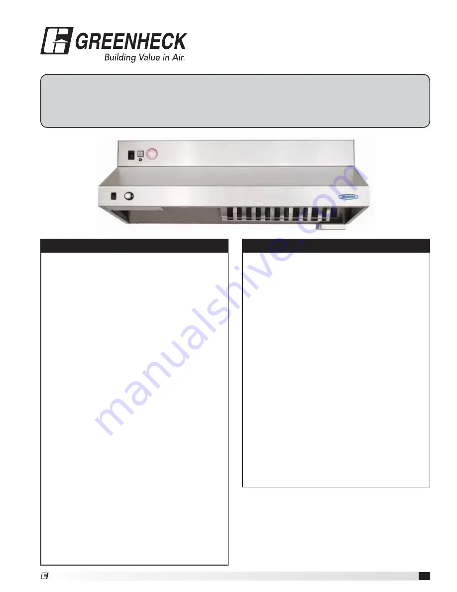
background image

1

Fire Ready Hood

Installation, Operation and Maintenance Manual

Please read and save these instructions for future reference. Read carefully before attempting to assemble, install, 
operate or maintain the product described. Protect yourself and others by observing all safety information. Failure 
to comply with instructions could result in personal injury and/or property damage!

WARNING

To reduce the risk of fire, electric shock, or injury 
to persons, observe the following:

•  Use this unit only in the manner intended by the 

manufacturer. 

•  Before servicing or cleaning unit, switch power off 

at service panel and lock the service disconnecting 
means to prevent power from being switched on 
accidentally. When the service disconnecting means 
cannot be locked, securely fasten a prominent 
warning device, such as a tag, to the service panel.

•  Installation work and electrical wiring must be 

done by a qualified person(s) in accordance with all 
applicable codes and standards, including fire rated 
construction codes and standards.

•  Sufficient air is needed for proper combustion 

and exhausting of gases through the flue 
(chimney) of fuel burning equipment to prevent 
backdrafting. Follow the heating equipment 
manufacturer’s guideline and safety standards such 
as those published by the National Fire Protection 
Association (NFPA), and the American Society 
of Heating, Refrigeration and Air Conditioning 
Engineers (ASHRAE), and the local code authorities.

•  When cutting or drilling into wall or ceiling, do not 

damage electrical wiring and other hidden utilities.

•  To reduce the risk of fire or electric shock, do 

not use this range hood with an additional speed 
control device.

•  Ducted fans must always be vented to the 

outdoors.

•  To reduce the risk of fire, use only metal ductwork.

•  Use with approved wiring only.

•  This unit must be grounded.

WARNING

To reduce the risk of range top grease fire:

•  Never leave surface units unattended at high 

settings. Boilovers cause smoking and greasy 
spillovers that may ignite. Heat oils slowly on low or 
medium settings.

•  Always turn hood ON when cooking at high heat or 

when cooking flaming foods.

•  Clean ventilation fans frequently. Grease should not 

be allowed to accumulate on fan or filter.

•  Use proper pan size. Always use cookware 

appropriate for the size of the surface element.

To reduce the risk of injury to persons in the event 
of a range top grease fire, observe the following:*

•  SMOTHER FLAMES with a close-fitting lid, cookie 

sheet, or metal tray, then turn off the burner. BE 
CAREFUL TO PREVENT BURNS. If the flames do 
not go out immediately, EVACUATE AND CALL THE 
FIRE DEPARTMENT.

•  NEVER PICK UP A FLAMING PAN. You may be 

burned.

•  DO NOT USE WATER, including wet dishcloths or 

towels - violent steam explosion will result.

* Based on “Kitchen Fire Safety Tips” published by 

NFPA.

®

®

Model GRRS

Fire Ready Hood

Summary of Contents for GRRS

Page 1: ...ssociation NFPA and the American Society of Heating Refrigeration and Air Conditioning Engineers ASHRAE and the local code authorities When cutting or drilling into wall or ceiling do not damage electrical wiring and other hidden utilities To reduce the risk of fire or electric shock do not use this range hood with an additional speed control device Ducted fans must always be vented to the outdoors...

Page 2: ... accepting delivery Alert the carrier of any damage detected The customer will make notation of damage or shortage of items on the delivery receipt and all copies of the bill of lading which is countersigned by the delivering carrier If damaged immediately contact your Greenheck Representative Any physical damage to the unit after acceptance is not the responsibility of Greenheck Fan Corporation U...

Page 3: ...ional 6 ft shielded control wire for plug and play connection Electrical disconnect box optional 6 ft shielded control wire for plug and play connection 8 ft of metal clad wire for gas disconnect electrical disconnect connection marked with black tape Remote switches ADA optional Manual Pull Kit optional consisting of the following Pull Box 1 Pull Face 1 Elbow Pulley 3 25 ft Cable and Pin The Cloc...

Page 4: ...e to Fan provided Power Disconnect Cable provided 110 VAC Supply Cable provided Wall Mount Fan Box with Access Cover for Service and Mounting provided Wall Mount Fan Box with Access Cover for Service and Mounting provided Cabinet Wall Cap by others Range Hood provided Airflow 3 x 12 in Ductwork Soffit Power Disconnect Cable provided 110 VAC Supply Cable provided Cabinet Range Hood provided Airflow So...

Page 5: ... 35 feet Yes Exterior Wall Fan Vertical Duct 550 20 feet Maximum duct length equals horizontal and vertical duct runs plus duct components such as fittings elbows and transitions For installations requiring vertical duct venting to an inline fan and NFPA 101 compliance the hood should be adapted from a 7 inch round duct access hole to a minimum 12 inch duct For installations requiring vertical duct...

Page 6: ...h the fan box Accessories Location restrictions will apply if the hood system supplied is provided with any of the optional accessories ClockBox Remote ADA Switches Manual Pull Station 2 Attach square duct collar to the bottom of the fan box with included hardware 3 Attach the fan box to the mounting bracket with included 8 32 nuts then complete the installation on the manual pull kit conduit and ...

Page 7: ...ting points must be secured to studs or drywall hangers C Rear access to junction box connection D Primary access point for connections to junction box E Secondary access point for connections to hood options accessories F Additional mounting points Secure minimum of three 3 screws per row Cabinet Front Cabinet Front Cabinet Bottom Electrical Access Hole 7 inch Round Duct Access Hole C L 5 15 16 i...

Page 8: ...ove the safety key from the actuator arm by rotating and lifting straight upwards The system will not actuate without completing steps 4 and 5 6 Rotate hood to wall and thread the three thumb nuts to the bolts in the mounting plate Check page 17 for location of thumb nuts Installing Hood onto Mounting Bracket 4 Remove the safety pin identified with the yellow CAUTION flag from the trigger on top of ...

Page 9: ...inlet and outlet flanges Wall Mounted Fan Fasten the fan box to an external wall via the four 0 27 inch mounting holes Run electrical through the 0 81 inch hole towards the top right corner of the box Attach ductwork using duct sealant caulk or tape to all seams to prevent air leakage and maximize air performance For best results use as few elbows or transitions as possible If necessary long radius...

Page 10: ...e of the face plate Given this the hole should be about 6 3 8 by 8 3 4 inch The relay box has been designed to fit in a standard 2x4 studded wall 2 If you haven t already done so run wiring from the junction box location on the unit mounting plate to the power disconnect box location and string through one of the knockouts in the box 3 Make all wiring connections and secure face plate to box in wal...

Page 11: ...nd Pin to hood Thread the cable through the conduit with the pin reaching the unit Remove the grease filter In the upper right corner find the two pulleys as illustrated Hold the rear most pulley in place From the top of the unit replace its pin with the one on the cable Push the pin through the pulley until you hear it click in place Go back to the actuator arm and rehook cable onto the arm Step 4 ...

Page 12: ...reaker to prevent electrical shock when accessing electrical connections All field installation and wiring of electrical equipment must be done to meet NEC and local codes Electrical Installation Range Supply Line 208 220 VAC 50A max supplied by others Hood Supply 110 120 VAC 15A Metal clad wire from 110 120 VAC supply line 12 2 8 ft length marked with red tape supplied by Greenheck Run metal clad...

Page 13: ...120 VAC Supply Line Red Tape Green Ground Wire nut inside power disconnect box Green Ground Black Hot 110 120 VAC 14 2 Hood White Neutral Black Hot 110 120 VAC Junction Box White Neutral Contactor 50A Supplied Power Disconnect Box 8 x 6 x 4 Back Support Mounting Bracket GND NEUT HOT GND NEUT HOT H N H H H Metal Clad Wire from 110 120 VAC Supply Line Red Tape 6 Position Orange Connector 6 Position ...

Page 14: ...r one connection or both depending on your situation When there is a fault a buzzer in the unit will sound and the power disconnect will turn off Local Alarm Connection Connect to output Y0 and common C0 Remote Alarm Connection Connect to output Y1 and common C1 To connect to the alarms it is preferred that you use a spade terminal connector supplied but a stripped wire is acceptable Connecting th...

Page 15: ...ow Blow MP1 Main Power Connector FP2 Fan Connector SW1 Main Power Switch SW2 Light Switch SW3 Service Switch SW4 Reset Switch SW5 Optional ADA Light SW6 Optional ADA Fan HSW1 Hose Switch HITH1 High Temp Thermostat 190 F LOTH1 2 Low Temp Thermostat 150 F FSP1 Fan Speed Controller 4 0 FLA FAN Inline or Recirc Fan CAP1 For Recirc Fan 10 UF M1 Stove Disconnect 40 FLA 50 A RES LIGHT Hood Light 60 WATT ...

Page 16: ...l system is not enabled and this reset button needs to be pressed In doing so the Status LED below the reset switch will turn from red to green Environmental Monitoring Pre Suppression Functions The controller operating system is designed to enhance the functionality of the unit and the safety of the cooking environment The system relies on input from a set of thermostats to control the fan and sh...

Page 17: ... On ducted installations remove the two thumb nuts located at the top inside near the fan intake Slowly lower the unit 4 The unit will now freely pivot downward to a stop position A safety cable is provided to prevent the unit from falling or lowering too far 5 Place safety pin in the tank valve to avoid accidental discharge With the unit in this position basic servicing and cleaning may be perfor...

Page 18: ...talled Remove the plastic break rod from the pull face with an allen wrench refer to manual pull station appendix for more detailed information on this Pull the handle to actuate the unit Refer to the Manual Pull Kit section on the method to return the pull station to an operational state 2 The unit can be actuated one of two ways A Cut Test Links Replace the actuator arm s safety key Loosen the t...

Page 19: ...rn the service switch to off for normal operation NOTE LED will flash orange and green Service Switch in the OFF position LED Label Input Function Scenario LED State X0 Hose Switch Hose in place On Hose disconnected Off X1 Reset Switch When switch is depressed On Switch not pressed Off X2 Pressure Switch Pressure okay On Pressure failure Off X3 Service Switch Servicing unit On Normal operation Off ...

Page 20: ...ns on for 3 minutes after you lower temperature or put red wire back on h Hood remains powered Self Monitoring System These functions are to be checked at start up Low Temperature Switches HOW TO TEST FUNCTION a Use heat gun on either left or right low temp switch b Fan turns on c Fan remains on for three minutes after temperature falls below 150ºF High Temperature and Low Pressure Switches HOW TO...

Page 21: ...ing before attempting any cleaning Using water to clean any appliance that contains hot grease or cooking oils may result in violent steaming or splattering How to Reset the Suppression System Resetting and testing release mechanisms remote pull and fusible links Reset detection system by completing the following steps 1 Remove extinguisher tank 2 Make sure tension arm cable is in the released sla...

Page 22: ... will energize into its normal operating open position 2 Examine burners for gaseous odor If gas odor exists turn off power switch which will cause the gas valve to close and shut off gas supply Clear gas fumes by opening windows and doors and then correct gas leak before proceeding 3 Reset gas valve again and if there is no gaseous odor pilot lights may be ignited at this time Gas stoves with a p...

Page 23: ... or after 12 months of use Inspection Procedures Maintaining the System WARNING The protective caps stay on the nozzles at all times In the event of a discharge the caps will blow off WARNING If grease build up on the cable system is not kept to a minimum the cable could become stiff and will not discharge the suppressant in the event of a fire 10 Year Maintenance Hydrostatic testing and new liqui...

Page 24: ...Fax 715 355 2399 Parts 800 355 5354 E mail gfcinfo greenheck com Website www greenheck com AMCA Publication 410 96 Safety Practices for Users and Installers of Industrial and Commercial Fans provides additional safety information This publication can be obtained from AMCA International Inc at www amca org As a result of our commitment to continuous improvement Greenheck reserves the right to chang...

Reviews: