background image

Rev

.01/03

1300

R

www.green-technik.com

[email protected]

By: GREEN-PRODUZIONE s.r.l.

Via Mons. Vigolungo, 2 - 12040 VEZZA D'ALBA -

R

AZIENDA CON SISTEMA QUALITÀ

CERTIFICATO

=

=

UNI EN ISO 9001/2008
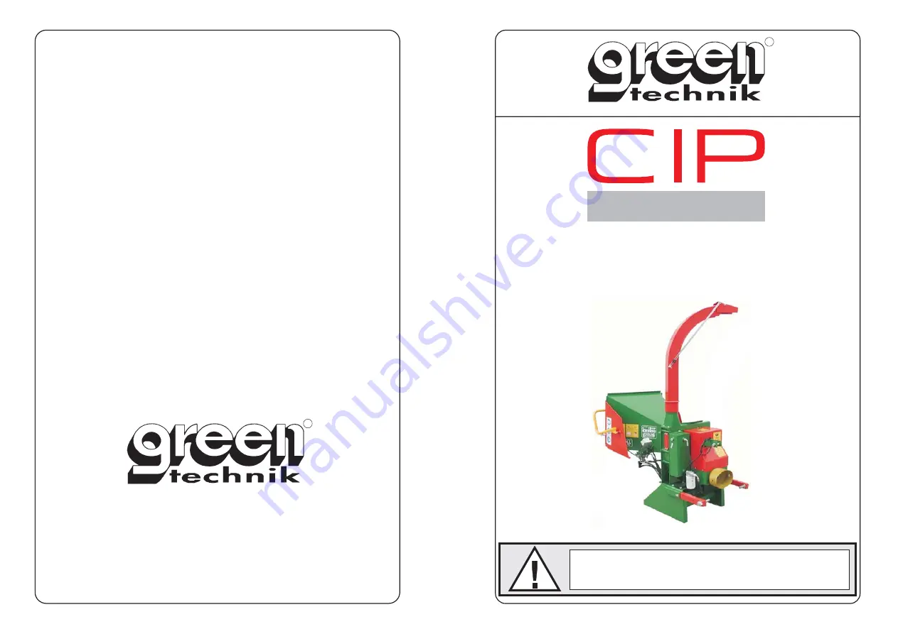
PROFESSIONAL

CHIPPER

OPERATION AND

MAINTENANCE HANDBOOK

CAUTION !

Befor using the machine, carefully read this Handbook!

Summary of Contents for CIP 1300

Page 1: ...technik com By GREEN PRODUZIONE s r l Via Mons Vigolungo 2 12040 VEZZA D ALBA R AZIENDA CON SISTEMA QUALITÀ CERTIFICATO UNI EN ISO 9001 2008 PROFESSIONAL CHIPPER OPERATION AND MAINTENANCE HANDBOOK CAUTION Befor using the machine carefully read this Handbook ...

Page 2: ...7 2 6 Keeping the manual 7 2 7 Information for the User 8 03 Technical description of the machine 9 04 Basic parts of the machine and their positions 10 05 Safety guards and protection devices 11 06 Residual risks concerning the machine 12 6 1 Considerations regarding safety conditions and residual risks 12 07 Transporting the machine 14 08 Checks 15 09 Starting the machine 16 10 Using the machine...

Page 3: ...bricating the mobile roller running guides 28 11 12 Lubricating the coupling collar of the discharge conveyor 28 11 13 Checking and replacing the multiplier oil PTO version 28 11 14 Checking the tension of Replacing the transmission belt Tractor PTO version 29 11 15 Checking the tension Replacement of the transmission belt motorised version 30 12 No Stress Device 31 12 1 Adjustment of the No stres...

Page 4: ...romise the integrity of the machine These are shown in italics WARNING This term on the hand is used to identify eventualities that can compromise the safety of the operator These are shown in italics and in some case in bold N B In all the chapters of this Instruction Manual the location of the accessories and the various parts of the machine is always given as in the diagram shown below LEFT SID...

Page 5: ...ll the maintenance adjustment and replacement operations described in this Manual must only be carried out after stopping the machine During blade removal adjustment and replacement operations the operator must wear protective gloves to avoid possible accidents The manufacturer of the machine supplies a pair While processing is being carried out the operator is required to wear anti noise muffs gi...

Page 6: ...on so as to warn the operator about residual risks during operation While moving the machine in its travel position there is the risk of it overturning You must therefore check beforehand the slopes and unevenness of the route to be taken before attempting to move the machine The path taken must not have a gradient greater than 5 Do not allow persons not authorised and not assigned to the work to ...

Page 7: ...distribution in whole or in part in any form print photocopy microfilm or other means and also its elaboration reproduction or distribution via systems or legal or physical persons without its approval and recording 2 2 Regulatory references When putting together the Manual indications contained in the following documents have been used Directive 2006 42 CE Appendix and modifications UNI EN ISO 12...

Page 8: ...In particular it must always be possible to consult it for the following information Intended conditions of use of the machine The work position occupied by the operator Instructions relating to Putting the machine into operation its use transportation installation assembly and disassembly adjustment maintenance and repair work and any training instructions there may be 2 5 Complying with legislat...

Page 9: ...ustomer who shall install it to the required standard and fit for the purpose for which it is to be used 5 The Manufacturer considers itself relieved of any responsibility where the machine has been put to Q improper use Q use by untrained staff Q use contrary to what is set out in this Manual Q use contrary to Regulations and Legislation currently in force Q use with a mains power supply defect Q...

Page 10: ...that further reduces the splinters into chips The chips through the centrifugal action of the cutting disk are projected into a discharge conveyor The conveyor can be pointed in the required direction of discharge Technical features size of loading mouth mm 960 x 670 MAX shreddable diameter mm 130 diameter of flywheel mm 680 thickness of flywheel mm 25 blades n 2 rotation speed of flywheel max g m...

Page 11: ...CIP 1300 Use and Maintenance Manual 10 Chapter 4 BASIC PARTS OF THE MACHINE AND THEIR POSITIONS DISCHARGE DEFLECTOR LOADING MOUTH CONTROL BAR CHASSIS ENGINE LAUNCH TUBE TOW BAR ...

Page 12: ...emoved for any reason A Fixed guards to close off the flywheel rotation area B Hydraulic motor side protection case C Hydraulic pump rear protection case D Transmission belt fixed guard PTO version CIP 1300PTO E Transmission belt fixed guard Motorised version CIP 1300Y18 1300H24 N B the guards must in no way be removed when carrying out maintenance switch off the engine and remove the key from the...

Page 13: ...K REFERENCE CHAPTER During processing the guards must not be removed for any reason CHAPTER 5 Protection guards and devices adopted for safety reasons In particular the fixed guards that close off moving parts whether of transmission or work must not be removed During installation check that the ground is sufficiently hard to ensure the stability of the machine Pay the greatest attention that no o...

Page 14: ...maintenance work CHAPTER 12 Using the machine Before any adjustment or maintenance operation switch off the engine and remove the key from the control panel CHAPTER 14 Ordinary and extraordinary maintenance Never rotate the flywheel with your hands Before putting your hands near the blades or the counter blade make sure the flywheel is completely still CHAPTER 10 Take all the necessary precautions...

Page 15: ...th a crane the size of lifting cable must be suitable for the weight of the machine in order to operate in conditions of complete safety When the machine has to be placed onto a means of transport it is possible to lift it by means of a crane To carry out the crane manoeuvre in safety the following procedures must be followed check the overall weight of the machine consult chapter 3 Technical Feat...

Page 16: ... R N I N G S Check that The operator is qualified to use the machine The operator is well acquainted with how to use the machine before setting it in motion The operator and the auxiliary staff are aware of the accident prevention regulations The operator is at least 18 years of age The operator wears close fitting clothes The operator wears protection equipment for ears and eyes and uses protecti...

Page 17: ...m does not exceed 16 and at PTO 1000 rpm does not exceed 9 Connect the machine to the three attachment points of the tractor Insert the security pins B C D Connect the cardan shaft to the power take off of the tractor and to the entry shaft of the machine A Check that the locking pins have engaged N B Check that the cardan shaft has a minimum axial play of 10 cm G Check the rotation direction R Im...

Page 18: ... or a protective visor ear muffs and safety shoes 10 1 Positioning the discharge conveyor After putting the machine into the working position the position of the discharge conveyor needs to be adjusted to direct the outflow of chipped material Slacken knob M Turn the conveyor into the desired direction grasping the lever L The conveyor can rotate on itself 360 Tighten knob M Slacken knob P Adjust ...

Page 19: ... pulled inside the machine Should this happen invert the direction of rotation of the rollers by pushing forward the control handle of the distributor 10 2 Control bar The device allows the operator to control the 2 feeder rollers Position 3 FORWARD The rollers rotate and pull the material towards the working disk Position 2 STOP The rollers stop and prevent the material from advancing forward tow...

Page 20: ... rollers by pushing forward the control handle of the distributor Start the engine following the procedures shown in the specific use and maintenance handbook and let it warm up for a few minutes at low revs Pull the control bar of the distributor into position 3 FORWARDS The feeder rollers are made to rotate A Introduce material to be shredded into the loading hopper The progress of material towa...

Page 21: ...ction of rotation of the rollers by pushing forward the control handle of the distributor using the machine continued If the material to be treated is short or difficult to advance push it towards the entry section with the help of a piece of wood If material becomes clogged at the entrance invert the direction of rotation of the rollers by pushing the control bar of the distributor into position ...

Page 22: ...the flywheel by hand Before putting your hands near the blades or the counter blade make sure the flywheel is completely still 10 3 Clogging of the discharge mouth Switch of the engine and make sure the flywheel has come to a complete standstill Remove the four M10 fixing screws and take off the discharge tube A With the aid of a hooked tool extract the material that has accumulated at the entranc...

Page 23: ...r put your hands near the entry section Take all the necessary precautions to avoid being caught up with the material that is being pulled inside the machine Should this happen invert the direction of rotation of the rollers by pushing forward the control handle of the distributor 11 1 Adjusting the rotation speed of the rollers You adjust the rotation speed of the pulling rollers by turning the v...

Page 24: ...rotective gloves and glasses or a visor CAUTION Never rotate the flywheel by hand Before putting your hands near the blades or the counter blade make sure the flywheel is at a complete standstill 11 2 Immobilising the flywheel for maintenance operations N B before setting about adjusting the blades or the counter blade or replacing them for sharpening it is necessary to immobilise the flywheel in ...

Page 25: ...erial and for the machine to operate properly To adjust the cutting unit proceed as follows Switch off the engine and make sure the flywheel has come to a complete standstill Remove the protective casing of the hydraulic motor C and fix the mobile roller in the raised position by inserting the spacer D provided Open the Hopper T as shown in the figure Slacken the fixing screws of the counter blade...

Page 26: ...heel has come to a complete standstill Undo the four M8 screws of the inspection panel A and remove it Immobilise the disk D as described in paragraph 11 2 Undo and extract the fixing screws of the blade V Check the blade C if the opposite cutting edge is sharp you only have to invert the position and fasten it If it is not replace it with a new or sharpened blade Repeat the procedure for the rema...

Page 27: ... for operations to have access to the counter blade Remove the screws V of the counter blade C and extract it Fit a sharp counter blade Proceed with adjusting the counter blade as described in paragraph 11 3 Fasten the counter blade with the screws V N B Take every precaution before starting to make adjustments ensuring that the flywheel is completely still and that the immobilising wedge is inser...

Page 28: ...sual oil level indicator A Check the level periodically and when necessary top up with Roloil LI 46 The oil must be replaced every 800 hours of operation or every 18 months To replace it proceed as follows unscrew the plug of the tank T unscrew the bottom drainage plug taking care to collect the oil with a receptacle put back the drainage plug put oil into the tank until it reaches the level shown...

Page 29: ...ease onto the flywheel supports V 11 11 Lubricating the mobile roller running guides With a brush apply an abundant layer of lithium based grease to the running guides of the mobile roller support G 11 12 Lubricating the coupling collar of the discharge conveyor Periodically spread lithium based grease onto the coupling collar C of the conveyor to make it easier to position 11 13 Checking and repl...

Page 30: ...n belt TRACTOR PTO version To carry out the operations listed below it is necessary to remove the protective casing A Check the tension of the belt by pressing it with your hand If it lowers more than 15 mm the tension must be adjusted T Slacken the four screws that fasten the multiplier to the structure V Slacken the fixing screw for adjusting along the slot B Check the efficiency of the belts an...

Page 31: ...ngine and make sure the flywheel has stopped completely Undo the screws of the protective casing C and remove it Check the tension T of the belts by pressing with your hand If the belt lowers by more than 15 mm the tension must be adjusted Check the efficiency of the transmission belts and if they are worn replace them proceeding as follows slacken the 3 screws of the engine support R slacken the ...

Page 32: ...hown by the lighting up of the rpm number of revs function and h hour counter function LEDs When the machine is in motion the No Stress device displays the number of revs per minute measured on the flywheel shaft via the sensor Ref E The device is already pre calibrated with values set by the factory However it is possible to reset the desired intervention SET1 and hysteresis SET2 threshold by pro...

Page 33: ...owing the procedure shown in par 11 5 3 The counter blade is not correctly adjusted 1 Adjust the counter blade following the procedure shown in par 11 3 4 The feeder speed is too high 1 Lower the feeder speed by turning the adjustment valve clockwise and if necessary invert the direction of rotation of the hydraulic rollers by putting the handle in the BACKWARDS position 5 None of the previous cau...

Page 34: ...BOLS CAUTION Read carefully chapter 1 2 WARNINGS The manufacturer has put in place on the machine various pictographs and symbols in compliance with legislation currently in force so as to warn the operator about residual risks that exist during the operation of the shredder ...

Page 35: ...CIP 1300 Use and Maintenance Manual 34 Chapter 15 ELECTRICAL SYSTEM 15 1 Electrical system of the NO STRESS device ...

Page 36: ...ine has an identification plate attached to the left side of the chassis on which are shown the model of the machine the serial number the year of construction the mark of conformity to the CE standards the name and place of the manufacturer the address and telephone number of the manufacturer ...

Page 37: ... in which we live Sheaths flexible pipes and components made of plastic or at any rate non metal material must be dismantled and disposed of separately The frame and indeed all the metal parts of the machine must be dismantled and grouped together by type of material The various parts thus obtained can be demolished and melted down to allow recycling of the material making up the original machine ...

Page 38: ...valid is the one shown on the fiscal document at the time of delivery of the machine by the retailer The company commits itself to repairing or replacing free of charge those parts which within the warranty period prove to be of defective manufacture Defects not clearly attributable to materials or manufacture will be examined at our Technical Assistance Centre or at our headquarters and charged f...

Page 39: ...e view of the manufacturer prove to be defective Any requests for compensation for damage caused by defects breakages or faults of the machine shall be rejected All those parts which are subject wear and tear and breakages attributable to improper use of the machine neglect or failure to carry out maintenance are excluded from the warranty For spark ignition engines attached to the machine the ter...

Reviews: