


Manufacturing, Inc.
www.greatplainsmfg.com
© Copyright 2019
Printed 4/25/19
195-144M
EN
ORIGINAL INSTRUCTIONS
Pre-Delivery Manual
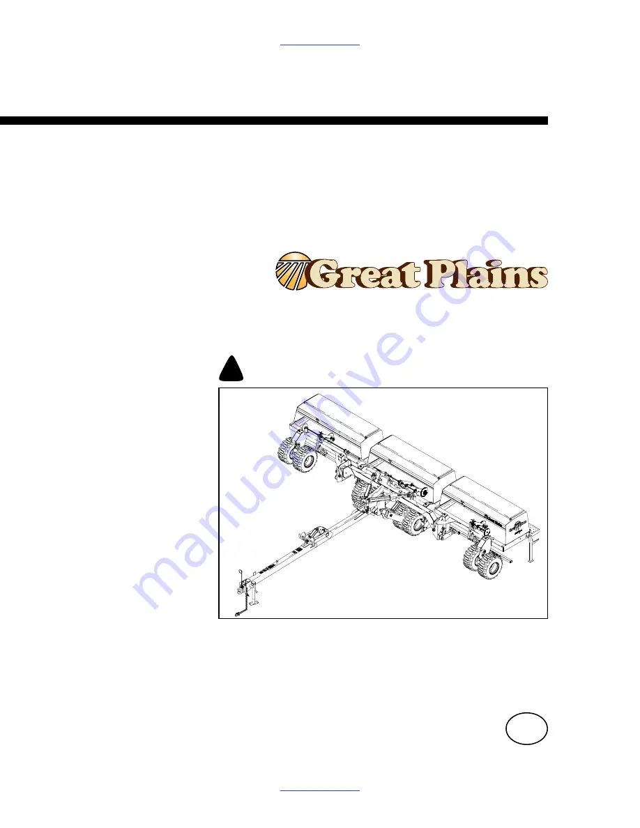
3S-3000
Three-Section Folding Drill
Read the operator’s manual entirely. When you see this symbol, the subsequent
instructions and warnings are serious - follow without exception. Your life and
the lives of others depend on it!
Cover illustration may show optional equipment not supplied with standard unit.
!
15485
Summary of Contents for 3S-3000 Series
Page 2: ...Table of Contents Table of Contents ...
Page 4: ...4 25 19 Table of Contents 195 144M 3S 3000 Table of Contents iv ...
Page 47: ...3S 3000 Table of Contents Appendix 43 4 25 19 Table of Contents 195 144M Point Row 22969 ...
Page 48: ...4 25 19 Table of Contents 195 144M 3S 3000 Table of Contents Appendix 44 ...
Page 49: ...Table of Contents Table of Contents ...
Page 50: ...Great Plains Mfg 1525 E North St P O Box 5060 Salina KS 67402 ...


