background image

cutting pro

FC4100


series

series

USER’S MANUAL

1

a

Summary of Contents for Cutting Pro FC4100-100

Page 1: ...cutting pro FC4100 series series USER S MANUAL 1 a...

Page 2: ...lor adhesive film at high speed The FC4100 Series FC4100 75 30 inches 75 cm wide FC4100 100 42 inches 100 cm wide FC4100 130 54 inches 130cm wide For more information about Graphtec and Graphtec produ...

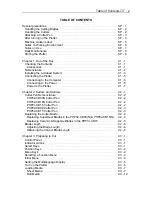
Page 3: ...otter C1 7 Chapter 2 Cutters and Holders C2 1 Cutter Pen Nomenclature C2 2 PHP32 CB09N Cutter Pen C2 2 PHP32 CB15N Cutter Pen C2 2 PHP31 CB15 Cutter Pen C2 2 PHP32 CB09 Cutter Pen C2 3 PHP32 CB15 Cutt...

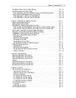
Page 4: ...o Change the Pen Quality C3 29 Pounce Conditions C3 30 To Change the Pounce Force C3 30 To Change the Pounce Speed C3 30 To Change the Pounce Quality C3 31 To Change the Pounce Offset C3 31 Light Poin...

Page 5: ...tings C5 1 The MENU TREE of Background Setting C5 2 Background Settings for GP GL C5 3 LANGUAGE SELECTION C5 3 Command Control COMMAND C5 3 Pen UP DOWN for the W Command C5 4 Condition Priority C5 4 I...

Page 6: ...tible Parallel Interface C7 6 Specifications C7 6 Electrical Characteristics C7 6 Input Output Circuitry C7 7 Input Output Timing Chart C7 7 Pin Assignment of the Parallel Connector C7 8 RS 232C Seria...

Page 7: ...Assemble the Basket C9 8 FC4100 Media Roll Holder Option C9 12 Contents C9 13 Assemble the Media Holders C9 13 Appendix AP 1 Information to the User AP 1 Compliance Information Statement AP 1 EC Decla...

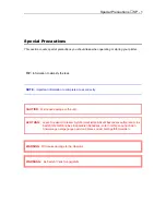
Page 8: ...tant information to complete a task correctly CAUTION Will cause damage to the unit ACHTUNG Lesen Sie den mit diesem Symbol markierten Absatz besonders aufmerksam Es besteht die Gefahr eines irreparab...

Page 9: ...n be careful to avoid cutting your fingers or other parts of your body n Die Messereins tze sind sehr scharf Um Verletzungen vorzubengen m ssen die Messereins tze mit vorsicht gehandhabt werden n Prom...

Page 10: ...tzen sollten Sie niemals das messer ber hren w hrend der Schneidplotter arbeitet Follow the procedure below to attach a cutter pen to the pen carriage 1 Make sure the pen holder screw is loose 2 While...

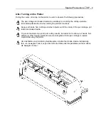
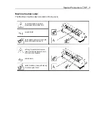
Page 11: ...ands hair clothing and other objects out of the vicinity of the pen carriage grit rollers and loaded media To prevent operator injury and poor cutting results be careful not to allow your hands hair c...

Page 12: ...top cover CAUTION REFER TO USER S MANUAL BEFORE OPERATION SHARP POINT KEEP HANDS HAIR AND CLOTHES AWAY FROM MOVING PARTS Achtung F r weitere Informationen lesen Sie bitte diese Handbuch bevor Sie mit...

Page 13: ...t of the pen carriage or loaded media may prevent accurate cutting or may trigger the position alarm to reset the system or system overload An overloaded system triggers the product s circuit protecti...

Page 14: ...le conforms to the EIA standard Inadequate grounding may result in severe damage to your plotter or computer and constitute misuse of the plotter n Never lubricate the plotter mechanisms it will resul...

Page 15: ...ing mat using a dry cloth In case of stubborn stains use a cloth that has been moistened in alcohol or in a neutral detergent diluted with water n Clean the plotter s paper sensors using a cloth moist...

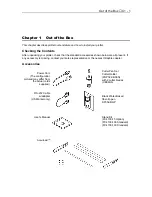
Page 16: ...esent If any accessory is missing contact your sales representative or the nearest Graphtec dealer Accessories Power Cord The configuration pictured may differ from the actual cords supplied Cutter Pe...

Page 17: ...to sense the trailing edge of the media 9 Parallel Interface Connector Used to connect the plotter to the computer with a Centronics compatible parallel interface cable 10 Pen Carriage Moves the pen a...

Page 18: ...ew at the second hole from the front side of the plotter NOTE Do not over tighten so that the bracket can rotate easily ASSEMBLY TIP When attaching the bracket on to the cutter use the foam shipping c...

Page 19: ...into the holes on the rear side of the media brackets NOTE Be sure to tighten all the screws to ensure accurate media loading The Accuload system may not function properly if even one of the screws a...

Page 20: ...er and tighten the screws If you are using a Centronics compatible parallel interface cable connect the 36 pin connector to the Parallel connector on the plotter and lock the levers 2 Connect the 9 pi...

Page 21: ...00 Plotter is equipped with a Power Cord in the Accessory Kit 1 Connect power cord to the plotter 2 Connect one end of the power cord provided to an electrical socket of the rated supply voltage then...

Page 22: ...ion to the desired interface conditions if the RS 232C serial interface is used command mode and programmable resolution 3 Connect one end of the power cord provided to an electrical socket of the rat...

Page 23: ...HP32 CB15N or PHP32 CB15 For cutting media which is too thick for the CB09UA blade to handle Suitable for cutting media from 0 25 mm to 0 5 mm thick CB15U K30 supersteel 1 5 mm 0 75 PHP32 CB15N or PHP...

Page 24: ...To avoid injury handle cutter blades carefully PHP32 CB09N Cutter Pen For cutter blades of 0 9 mm diameter PHP32 CB15N Cutter Pen For supersteel cutter blades of 1 5 mm diameter PHP31 CB15 Cutter Pen...

Page 25: ...Cutters and Holders C2 3 PHP32 CB09 Cutter Pen For cutter blades of 0 9 mm diameter PHP32 CB15 Cutter Pen For supersteel cutter blades of 1 5 mm diameter...

Page 26: ...lor classification Compatible blade types Blade material Cutter offset values PHP32 CB09 Blue CB09UA Supersteel 18 2 PHP32 CB15 Red CB15U CB15U K30 Supersteel Supersteel 28 2 28 2 PNP31 CB15 Red CB15...

Page 27: ...hly or the blade falls off after attaching the cutter pen to the pen carriage the inside of the holder is insufficiently lubricated Apply grease provided to the three 3 points indicated by arrows in t...

Page 28: ...ob in a clockwise direction A direction until the blade tip reaches a suitable length 2 Observe the scale on the plunger cap to determine how far to move the blade When the knob is turned the distance...

Page 29: ...mps The POWER lamp remains lit green while the plotter is on The PROCESSING INDICATOR lamp lights green when the cutting data goes beyond the effective cutting area Select Keys Soft keys are keys whos...

Page 30: ...ctions and Settings for details Press COPY to repeat the cutting operation defined by the data in the plotter s receive buffer See the section COPY in Chapter 4 Advanced Functions and Settings for det...

Page 31: ...Preparing to Cut C3 3 Press AXIS ALIGN to get into the axis alignment adjustment mode See the section Axis Alignment in Chapter 4 Advanced Functions and Settings for details...

Page 32: ...N UP DOWN BUFFER CLEAR FEED NEXT INTERFACE STEP SIZE GP GL only RS 232C COMMAND AREA PARAMETERS ORIGIN GP GL only AREA EXPAND PAGE LENGTH FUNCTION 1 ROTATE MIRROR SCALE FUNCTION 2 DATA SORTING AXIS AL...

Page 33: ...age Turn the power on while pressing the DOWN ARROW key and the Menu selection display then appears Press the UP and DOWN ARROW keys to scroll through the languages Danish Dutch English French German...

Page 34: ...nd selected command set The screen displays either GL or HL The GL shows that the GP GL Command set is selected and the HL shows that the HP GL command set is selected If you have already loaded media...

Page 35: ...e pen carriage out of the way while the power is off After the first initialization use the arrow keys to move the pen carriage Sheet Media CAUTION To avoid damaging the cutting mat make sure to set t...

Page 36: ...Preparing to Cut C3 8 c Wrap media behind and around the media alignment shaft While keeping tension on the vinyl adjust the vinyl edges so that both edges match accurately...

Page 37: ...media to the left or right be sure to move the pinch rollers as required to hold down the media within the appropriate range n Be sure to position the pinch rollers so that they are not located right...

Page 38: ...Middle Pinch Rollers will effect the performance of the FC4100 100 and FC4100 130 Cutting Plotters n Lower the media set lever to raise the pinch rollers n Move the left pinch roller next to the midd...

Page 39: ...GL Buffer RAM checking 3 Then lower the pinch rollers raise the lever and pull the vinyl out from the alignment bar 4 Turn on the Power if it is off 5 Plotter performs the initialization routine 6 Loa...

Page 40: ...1 Load the Media a Place the roll of media on the media stocker Use the yellow markings to locate the grit rollers Place the media so that its edges align with the grit rollers b Lower the media set...

Page 41: ...o Cut C3 13 c Load the media in the plotter as shown d Wrap media behind and around the media alignment shaft While keeping tension on the vinyl adjust the edges of the vinyl so that both edges match...

Page 42: ...to ensure that no slack develops in the media n When moving the media to the left or right be sure to move the pinch rollers as required to hold down the media within the appropriate range n Be sure t...

Page 43: ...Middle Pinch Rollers will effect the performance of the FC4100 100 and FC4100 130 Cutting Plotters n Lower the media set lever to raise the pinch rollers n Move the left pinch roller next to the midd...

Page 44: ...the front of the plotter should be sufficient to completely cover the paper sensor If the front edge extends too far when you have pulled the media taut wind the media back onto the roll NOTE To view...

Page 45: ...s feed function to feed out the specified amount of media n Before your start a long length cutting operations hand feed out the length that will be required for the cutting operation Let the media si...

Page 46: ...ng edge of the roll media is not detected and the coordinate origin is initialized with respect to the cutting mat Press F2 key to select ROLL 2 The initialization routine is executed to determine the...

Page 47: ...election is available from the second initialization after turning power on Therefore CONTINUE in the media selection menu does not appear on the first initialization after turning power on Plotter as...

Page 48: ...edge of the media SHEET 1 During initialization the pen carriage moves right until it detects the mechanical home position 2 The pen carriage then moves left until it detects the left hand side of the...

Page 49: ...selected conditions greatly affect the finished quality of cutting operations NOTE Raising the SPEED and QUALITY values result in lower precision but reduced overall cutting time This is useful when...

Page 50: ...OTE When you select POUNCE the cutter offset refers to the spacing between the holes Press the ENTER key to select the tool TANGENTIAL mode Besides cutter blade selection noted above you can select th...

Page 51: ...ails see Tangential Emulation To Change the Cutter Force Press the F1 key to change FORCE The blinking cursor indicates that you can change its setting Press the UP or DOWN ARROW key to raise or lower...

Page 52: ...PEED Press the F4 key to change OFFSET Press the ENTER key to register your setting To Change the Cutter Offset Press the F4 key to change OFFSET The blinking cursor indicates that you can change its...

Page 53: ...Cut the test pattern Test 1 Test 2 Cutting Pro in three locations the far right side the center and the far left side of the media 2 Check the shape of the pattern 3 Change the condition parameters i...

Page 54: ...you have almost achieved the best condition use the TEST 2 pattern This test cuts three triangle patterns in 3 different cutting forces The center triangle is cut using the force you selected The lef...

Page 55: ...edia loaded in the plotter and the READY or PAUSE mode displayed on the menu Press the TEST key on the Control Panel You will see the following test menu Press the F4 key to select CUTTING PRO Press t...

Page 56: ...60 4 Ceramic pen 7 to 8 20 2 Ink pen 4 to 7 10 2 NOTE The condition settings will vary according to the type of paper used To prolong the life of your pen keep the FORCE setting as low as possible Se...

Page 57: ...sec speed NOTE The selection is available with firmware version 1 13 or later Press the F1 key to change FORCE Press the F3 key to change QUALITY Press the ENTER key to register your setting To Change...

Page 58: ...rsor indicates that you can change its setting Press the UP or DOWN ARROW key to raise or lower the numeric value from 1 to 35 Press the F3 key to change QUALITY Press the F4 key to change OFFSET Pres...

Page 59: ...alue the higher the quality Press the F1 key to change FORCE Press the F2 key to change SPEED Press the F4 key to change OFFSET Press the ENTER key to register your setting To Change the Pounce Offset...

Page 60: ...stickers How to Point the Target The light point is projected on the media as a small red circle It allows you to see the position of the light point easily even though it is being placed on a large...

Page 61: ...he media will back up at the PEN UP SPEED when NORMAL is selected For details see FEED Advancing Media When the media set lever is lowered the following menu appears on the display Press the F4 key Pr...

Page 62: ...irm the job is completed While holding down the ENTER key press the UP ARROW key Repeat this process as needed to move the pen carriage away from the cutting plotting job Returning the Pen Carriage to...

Page 63: ...r more details see Setting the Interface Functions Command For more details see Setting the Interface Functions Area Parameters Origin to set the Origin in HP GL mode Area to specify the effective cut...

Page 64: ...rigin position Press the ORIGIN key The beeper sounds and the LCD displays a message indicating that the new origin is effective Origin Point with ROTATE function NOTE The coordinates being displayed...

Page 65: ...Press the COPY key to select the COPY mode If the data for copy is available in the receive buffer the following menu will appear If the receive buffer is empty the following message will appear Retur...

Page 66: ...to achieve the number the copies you wish to cut Then reset the copy function again Press the ENTER key the following menu will appear The plotter starts cutting plotting as soon as the ENTER key is p...

Page 67: ...e the sequence in which copies are cut with the shaded areas representing the parts of the media that are not cut If MIRROR mode is selected the copies are cut in this sequence If ROTATE mode is selec...

Page 68: ...trols the light pointer s light The light turns on when PEN DOWN is selected The light turns off when PEN UP is selected WARNING While using this function keep your hands out of the vicinity of the pe...

Page 69: ...red but the computer resumes sending subsequent data which remains in its buffer At such time the pen carriage may suddenly start moving so be sure to keep your hands face and other obstacles out of t...

Page 70: ...o starting cutting by this function Otherwise enable AUTO PRE FEED FUNCTION CAUTION Do not use the FEED function with media that is shorter than 1 meter If the FEED LENGTH setting exceeds the actual l...

Page 71: ...a Lower Left Origin Press the MENU key to select MENU mode Press the NEXT key Press the NEXT key again Press the F2 key to select AREA PARAMETERS Press the F1 key to select ORIGIN If there is no ORIG...

Page 72: ...o avoid injury keep your hands face and other obstacles out of the vicinity of the cutting mat and media Press the MENU key to select MENU mode Press the NEXT key Press the NEXT key again Press the F2...

Page 73: ...are initialized to their default position the lower left and upper right corners of the maximum effective cutting area unless CONTINUE is selected at the media type menu NOTE The LL and UR positions...

Page 74: ...xample the shaded area represents the effective cutting area defined by the LL and UR points When the ROTATE mode has been selected to rotate the coordinate axes by 90 as shown in the example the shad...

Page 75: ...e cutting area and a negative setting indicates the limit of both sides move toward the inside of the cutting area For example setting at 5 gives 10mm wider cutting area than the size of the default c...

Page 76: ...key to store your setting the following menu will appear If the F4 key is pressed return to the previous menu Press the F3 key to select CONTINUE Press the F4 key to select CANCEL If the CONTINUE is...

Page 77: ...Advanced Functions and Settings C4 15 Setting a negative expansion limit Setting a positive expansion limit...

Page 78: ...or the operation before you begin cutting or plotting unless the AUTO PRE FEED function is enabled Press the MENU key to select MENU mode Press the NEXT key Press the NEXT key again Press the F2 key t...

Page 79: ...key to select MENU mode Press the NEXT key Press the NEXT key again Press the F3 key to select FUNCTION1 Press the F2 key to select ROTATE Press the F3 key to turn ON the function Press the F4 key to...

Page 80: ...hroughput Use this function when the pen carriage and the media move back and forth excessively and their movement is not minimized by the application software If your application software is able to...

Page 81: ...ves the cut data from the PC If CANCEL is selected return to the previous menu Press the MENU key to cancel the menu mode NOTE The plotter begins sorting immediately when it receives the cut data from...

Page 82: ...a is cut Press the MENU key to select MENU mode Press the NEXT key Press the NEXT key again Press the F3 key to select FUNCTION1 Press the F3 key to select MIRROR Press the F3 key to turn ON the funct...

Page 83: ...arging or reducing an image to be cut or plotted Press the MENU key to select MENU mode Press the NEXT key Press the NEXT key again Press the F3 key to select FUNCTION 1 Press the F4 key to select SCA...

Page 84: ...ge and is the primary axis alignment tool n LOUPE Is a pen shaped magnifier associated with a cross cursor optional referred to as Bombsight This option must be swapped with the cutter holder METHOD T...

Page 85: ...bombsight has been selected neither the pen carriage nor the media will move evenly even though the AXIS ALIGNMENT key has been pressed because the loupe is already in the same position as the cutter...

Page 86: ...of the origin point individually as with the 2 point method and you may match the plotter s distance scale to that of the printed image To match the plotter s distance scale to that of the printed ima...

Page 87: ...ress the MENU key to select MENU mode Press the NEXT key Press the NEXT key again Press the F4 key to select FUNCTION 2 Press the F2 key to select AXIS ALIGNMENT Press the F3 key to select METHOD Pres...

Page 88: ...to select the Axis Alignment mode Then the Axis Alignment menu appears Press the POSITION key to move the light pointer or the loupe to the Axis Point 1 Press the ENTER key to store the setting The fo...

Page 89: ...Press the UP or DOWN key to increase or decrease the number of distance value Press the ENTER key to store the setting The following menu appears The light pointer or the loupe move back to the Axis...

Page 90: ...resume the cutting plotting job Please note that this function should be set before the cutting plotting job is started since changing the setting of this mode leads to the plotter s initialization as...

Page 91: ...y access the Auto pre feed menu from the initial menu which appears on the LCD when the paper set lever is lowered Press the F4 key to select the initial menu while the initial menu appears on the LCD...

Page 92: ...rcut function which eliminates uncut portions from thick material is available when the tangential emulation is enabled Be sure to set TANGENTIAL settings to suit the media being cut Selecting Tangent...

Page 93: ...pen condition Press the MENU key to select MENU mode Press the NEXT key Press the NEXT key again Press the F4 key to select FUNCTION 2 Press the F4 key to select TANGENT EMULATION Press the F4 key to...

Page 94: ...e NEXT key Press the NEXT key again Press the NEXT key again Press the F3 key to select OPTION 1 Press the F1 key to select PEN UP SPEED Press the UP or DOWN ARROW key to sequence through the availabl...

Page 95: ...y set the reference angle of connection and eliminate the blade control at the connections whose angles are under that reference angle Press the MENU key to select MENU mode Press the NEXT key Press t...

Page 96: ...ack a clear cut particularly when using very thin material Start from the default setting 4 first then change the value if necessary Press the MENU key to select MENU mode Press the NEXT key Press the...

Page 97: ...Press the NEXT key again Press the NEXT key again Press the F3 key to select OPTION 1 Press the F4 key to select STEP PASS Press the UP or DOWN ARROW key to sequence through the available choices The...

Page 98: ...AJUST Setting for the X axis to 0 5 increases the X axis by 1 mm Press the MENU key to select MENU mode Press the NEXT key Press the NEXT key again Press the NEXT key again Press the F4 key to select...

Page 99: ...er while pressing the DOWN ARROW key After setting the necessary items turn off the plotter regardless of the menu being displayed All settings are registered in the plotter s internal memory and reta...

Page 100: ...TY PEN UP MANUAL PEN DOWN PROGRAM CONDITION PRIORITY INITIAL BLADE CONTROL POSITION MANUAL 2mm BELOW PROGRAM OUTSIDE INITIAL BLADE LENGTH UNIT CONTROL POSITION 2mm BELOW METRIC OUTSIDE INCH LENGTH UNI...

Page 101: ...ting with no changes If you do not wish to make any changes on the background settings turn off the plotter Command Control COMMAND When the GP GL command mode is selected set this function to enable...

Page 102: ...u wish to bypass this setting with no changes If you do not wish to make any changes on the background settings turn off the plotter Condition Priority This function determines the priority of program...

Page 103: ...mm BELOW Press the F4 key to select OUTSIDE An asterisk appears beside your choice Press the ENTER key to register your setting and to proceed to the next menu Press the NEXT key if you wish to bypass...

Page 104: ...T key if you wish to bypass this setting with no changes If you do not wish to make any changes on the background settings turn off the plotter Media Size Sensor Control This function allows you to di...

Page 105: ...pinch roller position sensor will not perform In cases where the media length is disabled the pen carriage may go beyond the edge of the media Always set the AREA function to limit the cut area and t...

Page 106: ...sh to bypass this setting with no changes If you do not wish to make any changes on the background settings turn off the plotter Model No Response MODEL EMULATED When the HP GL command mode is selecte...

Page 107: ...the F4 key to select PROGRAM An asterisk appears beside your choice Press the ENTER key to register your setting and to proceed to the next menu Press the NEXT key if you wish to bypass this setting w...

Page 108: ...ttings turn off the plotter Pen UP Movement Control PEN UP MOVE When the Plotter receives commands that specify consecutive pen movements in raised status the PEN UP MOVE function determines whether t...

Page 109: ...next menu Press the NEXT key if you wish to bypass this setting with no changes If you do not wish to make any changes on the background settings turn off the plotter Pinch Roller Sensor Control This...

Page 110: ...LT is selected the resolution of circles and arcs is always 5 degrees If the circle or arc consists of short line segments the quality of the circle or arc will not change by this setting Press the F3...

Page 111: ...urrent settings at a glance WARNING The pen starts moving as soon as the CONDITON PRINT function is selected To avoid injury to yourself and damage to the plotter keep your hands face and other obstac...

Page 112: ...tout of the CONDITION function COND FORCE SPEED PEN TYPE OFST ACCL TNGNT OVCUT 1 12 30 PEN 0 4 OFF 2 14 30 CB09Ux 0 4 OFF 3 17 30 OTHER 17 4 ON 0 2 0 2 4 25 10 CB15Ux 0 1 OFF RS 232C BAUD RATE PARITY...

Page 113: ...am are identical check the program at the computer again If the cutting plotting results are not what you expected and the received data and the transmitted program are different check the interface c...

Page 114: ...lotting Press the F4 key to select CANCEL CONDITIONS You have to turn off the plotter to cancel DUMP if the plotter is in DUMP mode The following prompt message appears Transmit the data from the comp...

Page 115: ...T mode is executed To avoid injury to yourself and damage to the plotter keep your hands face and other obstacles out of the vicinity of the cutting mat and paper Load paper whose size is larger than...

Page 116: ...When you have finished printing the SELF TEST pattern turn off the plotter to cancel SELF TEST mode NOTE The self test pattern is repeatedly printed until the plotter is turned off To discontinue prin...

Page 117: ...he power cord and wait the recovery time can vary from case to case If the machine does not recover after 30 minutes contact your sales representative or nearest Graphtec dealer The plotter is defecti...

Page 118: ...the pinch rollers may not be set on the grit rollers Check the position of the pinch rollers Loading Media One side of media edge comes off from the pinch roller The front or rear edge of the media is...

Page 119: ...although the plot data is created based on lower left origin Check the origin setting Origin As soon as the data is sent to the plotter the media comes off then MEDIA END message appears ROLL 1 or RO...

Page 120: ...Media is abruptly fed forward Incorrectly selected media type Correctly set the media type to match your media Selecting Media The length of cutting results differs from the program slight distance er...

Page 121: ...the paper sensors Disable the paper sensors using media size sensor control in the background settings Media size sensor setting in the Background settings Strong reflected light is preventing the pa...

Page 122: ...he pen holder The Offset Cut Pressure is too low Raise the Offset Cut Pressure setting the Offset Cut Pressure is separate from the cutting force Offset Force With the 0 9 mm cutter pen blue blade adj...

Page 123: ...oo high Lower the SPEED Setting Setting Cutter Conditions The blade is dull Replace the blade Replacing Cutter Blade The QUALITY setting is too high Lower the QUALITY setting Setting Cutter Conditions...

Page 124: ...differ from specified size The programmable resolution STEP SIZE has been set differently at the plotter and the software application Set both the plotter and software to the same resolution Step Size...

Page 125: ...the Offset Cut pressure setting Setting the Cutting Conditions The media is too flimsy Switch to a stronger media Blade rotation is not smooth Grease the cutter blade and holder Replacing the Cutting...

Page 126: ...ter back on The pen carriage was subjected to external pressure during cutting Turn off the plotter remove the obstacle then turn the plotter back on Media scraps stuck in moving parts and impeding pl...

Page 127: ...arriage is being obstructed Turn off the plotter remove the obstacle then turn the plotter back on The pen carriage was subjected to external pressure during cutting Turn off the plotter remove the ob...

Page 128: ...sure that the software s interface conditions are correctly set The plotter s interface conditions have been changed Ensure that the plotter s interface conditions are set to match those of the softwa...

Page 129: ...ftware configuration regarding the output device has been changed Configure the software to drive your plotter Ensure that the software s interface conditions are correctly set The plotter s interface...

Page 130: ...nknown character set ERROR 6 Position overflow ERROR 7 Buffer overflow Cause Solution An unrecognizable instruction was executed Execute a recognizable command Cause Solution A command was executed wi...

Page 131: ...ESC command in your program Cause Solution A device control command containing an invalid byte was received Check the device control commands in your program Cause Solution A parameter outside of the...

Page 132: ...see Centronics Compatible Parallel Interface Setting the Serial Interface To enable prompt compatibility with multiple software applications you can register three different groups of interface settin...

Page 133: ...ore you have loaded media When the media set lever is lowered the following menu appears Press the F4 key to select INITIAL MENU Press F3 key to select RS 232C and the INTERFACE menu appears Press the...

Page 134: ...o set the distance of pen movement corresponding to the coordinate value of 1 NOTE Be sure to set the step size to match the step size setting of your software application NOTE Your step size setting...

Page 135: ...ss the F2 key to select factory setting 2 Press the F3 key to select factory setting 3 The asterisk is displayed beside the currently selected condition number The menu that corresponds to the number...

Page 136: ...your software application NOTE Your command setting is retained in the plotter s internal memory even while the plotter is turned off Press the F4 key to select COMMAND Press the F3 key to select GP G...

Page 137: ...ls to begin a cutting or plotting operation When the specified operation is completed the plotter awaits the input of subsequent DATA signals CAUTION The interface cable should be no longer than two m...

Page 138: ...Setting the Interface Functions C7 7 Input Output Circuitry Input Output Timing Chart...

Page 139: ...escribed below Pin No Signal Name Pin No Signal Name 1 STROBE 19 GND 2 DB 0 20 GND 3 DB 1 21 GND 4 DB 2 22 GND 5 DB 3 23 GND 6 DB 4 24 GND 7 DB 5 25 GND 8 DB 6 26 GND 9 DB 7 27 GND 10 ACK 28 GND 11 BU...

Page 140: ...nary data control signals and SYNC signals Specifications Standard CCITT V 24 EIA RS 232C JIS X5101 Synchronization Asynchronous start stop Transfer Rate 19200 bits s Stop Bit 2 stop bits Parity Even...

Page 141: ...3 RD RxD 16 Not used 4 RS RTS 17 Not used 5 CS CTS 18 Not used 6 DR DSR 19 Not used 7 GND LOGIC 20 ER DTR 8 Not used 21 Not used 9 Not used 22 Not used 10 Not used 23 Not used 11 Not used 24 Not used...

Page 142: ...k and disposable ink pens Pounce types 1 2 mm diameter pin Compatible media Mono vinyl chloride media fluorescent media and media for illuminated displays high reflective media 1 up to 0 25 mm thick S...

Page 143: ...mpatible media Mono vinyl chloride media fluorescent media and media for illuminated displays high reflective media 1 up to 0 25 mm thick Sandblast rubber up to 1mm thick 3 Standard interfaces RS 232C...

Page 144: ...Compatible media Mono vinyl chloride media fluorescent media and media for illuminated displays high reflective media 1 up to 0 25 mm thick Sandblast rubber up to 1mm thick 3 Standard interfaces RS 23...

Page 145: ...a basket Media Basket FC4100 100 Collapsible media basket Media Basket FC4100 130 Collapsible media basket Multi Media Supply Kit FC4100 75 Rollers Brackets Multi Media Supply Kit FC4100 100 Rollers B...

Page 146: ...Specifications C8 5 External Dimensions FC4100 75 without Stand FC4100 75 with Stand and Basket Option...

Page 147: ...Specifications C8 6 FC4100 100 without Stand FC4100 100 with Stand Standard and Basket Option...

Page 148: ...Specifications C8 7 FC4100 130 without Stand FC4100 130 with Stand Standard and Basket Option...

Page 149: ...k outline for graphics that will be hand painted The pounce tool has a small point that is pressed into the media The pounce conditions are set from the conditions menu Force Sets the hole punching fo...

Page 150: ...he pen holder screw is loose 2 While holding the pen holder upward push the pouncing tool all the way into the holder until its rim contacts the pen stopper The flat side of the tool must face the pen...

Page 151: ...o 35 3 Press the F3 key to change QUALITY 4 Press the F4 key to change OFFSET 5 Press the ENTER key to register your setting To Change the Pounce Speed 1 Press the F2 key to change SPEED 2 Press the U...

Page 152: ...with the conveyor rollers or media installed The unit becomes unstable when heavy loads are added In extreme cases the unit may tip over CAUTION Improper assembly of these pieces may cause the unit t...

Page 153: ...tand on a secure flat surface Tools M6 Hex Key 1 Attach Middle Bar to left side of the stand with two M6 x 16mm Socket Cap Screws 2 Attach Middle Bar to right side of the stand with two M6 x 16mm Sock...

Page 154: ...le set the plotter without the Conveyor Rollers and Media installed on the Stand assembly using the index pins to align on the left and right top mounting brackets of the stand 6 Secure unit with four...

Page 155: ...p over CAUTION Improper assembly of these pieces may cause the unit to become unstable when heavy loads are added In extreme cases the unit may tip over CAUTION The longer length leg platform is insta...

Page 156: ...on a secure flat surface Tools M6 Hex Key Mallet or Rubber Hammer 1 Attach Tube Bracket to the upper two holes in the left side of the stand with two M6 x 16mm Socket Cap Screws 2 Attach Tube Bracket...

Page 157: ...maining Basket Tube thru the bottom two holes of the Tube Brackets rear and front 6 Push the two Basket Tubes in all the way 7 Install the Tube Stoppers into the end of the Tubes use a Mallet or Rubbe...

Page 158: ...exit the openings clearly 9 Repeat on other end 10 Slide the Basket thru the Stand The velcro must face toward the bottom Position the Basket so that the Middle Bar is between the two sets of velcro 1...

Page 159: ...two people set the plotter without the Conveyor Rollers and Media installed on the stand assembly using the index pins to align on the left and right top mounting brackets of the stand 15 Secure unit...

Page 160: ...the Media using the outside Accuload roller as an idler 3 Make sure to feed the media correctly 4 Make sure to move the roll holders closer together as the rolls become smaller 5 Make sure to load ro...

Page 161: ...ia Holders The following information will give you step by step instructions on how to assemble the Media Holder Assembly for the GRAPHTEC FC4100 Cutting Plotter For the best results please follow all...

Page 162: ...two M6 x 12mm Socket Cap Screws 4 Insert the lower two conveyor rollers 5 Insert the middle two conveyor rollers 6 Insert the top two conveyor rollers NOTE Make sure the conveyor rollers are straight...

Page 163: ...ction against harmful interference when the equipment is operated in a commercial environment This equipment generates uses and can radiate radio frequency energy and if not installed and used in acco...

Page 164: ...uct Product Name Cutting Pro Model Number FC4100 75 FC4100 100 FC4100 130 Optional Accessory Stand and Media Basket CE Mark Applied 1999 to which this declaration relates is in conformity with the fol...

Page 165: ...2 1 CB15U Blade C2 1 CB15U K30 Blade C2 1 CB15 10C Blade C2 1 CB15 05S Blade C2 1 Centronics Interface C1 5 C7 6 Circle Resolution C5 12 Command Error Messages C6 18 Selecting C7 5 W Command C5 4 Comm...

Page 166: ...tor Lamps C3 1 Initial Blade Control Position C5 5 C5 9 Menu C3 4 Routine C3 20 Installing Accuload System C1 3 Basket C9 7 Cutter Pen SP 3 Media Roll Holder C9 12 Pounce C9 2 Stand C9 4 Interface C1...

Page 167: ...2 C3 18 Roll Media C3 12 Rotate C4 17 RS 232C SP 7 C1 5 C7 1 C7 4 C7 9 Running Cutting Test C3 25 S Scale C4 21 Select Keys C3 1 Select Function Menu C3 4 Media Type C3 18 Tool from the Menu C3 21 Se...

Page 168: ...D 4 U Unit Length C5 5 V W W Command C5 4 Withdrawal of the Pen Carriage C3 34 Working Environment SP 6 www graphteccorp com T 1 www graphtecusa com T 1 X Y Z Others Command Control C5 3 Command Contr...

Page 169: ...The specifications etc in this manual are subject to change without notice Printed in U S A Part No 53801 072T Rev B asd...

Reviews: