Graflex SUPER GRAPHIC, Installation, Service Instructions & Parts
The Graflex SUPER GRAPHIC user manual is an essential resource for camera enthusiasts. Packed with comprehensive "Installation, Service Instructions & Parts" guidelines, this manual ensures optimal use of your device. Easily accessible for "free download" on our website, manualshive.com, it provides step-by-step instructions to maximize your camera's features and functionality.
Share
Download


Reviews:
No comments
Related manuals for SUPER GRAPHIC

170
Brand: Olympus Pages: 69

SEMT-7680
Brand: Okina USA Pages: 3

HD21T-K10
Brand: Okina USA Pages: 16

IntelliSHOT
Brand: VADDIO Pages: 13
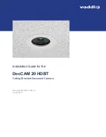
DocCAM 20 HDBT
Brand: VADDIO Pages: 5
DocCAM 20 HDBT
Brand: VADDIO Pages: 18

ClearSHOT 10 USB
Brand: VADDIO Pages: 62

RoboSHOT 12
Brand: VADDIO Pages: 41

DPF102
Brand: Abocom Pages: 1

HY-5099
Brand: TZT Pages: 12

DDF4900HDV Series
Brand: dallmeier Pages: 71

OEM-6400.FT
Brand: SecurView Pages: 4

MiVue 320
Brand: Magellan Pages: 105

DSJ-C11
Brand: CAMMHD Pages: 24

QV-780
Brand: Casio Pages: 41

SnapShot Extra
Brand: Doerr Pages: 6

IQeye R5 Series
Brand: Vicon Pages: 12

DP562 - Digital Photo Frame
Brand: Coby Pages: 44


