background image

Repair – Parts List

GRACO INC.ąP.O. BOX 1441ąMINNEAPOLIS, MNą55440-1441

Copyright 2003, Graco Inc. is registered to I.S. EN ISO 9001
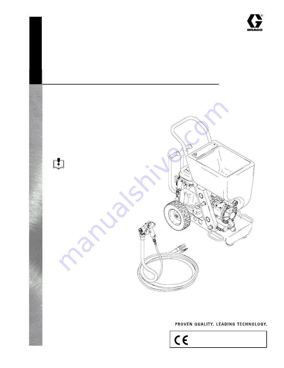
TexSpray GTX

t

 2000

– For Water-Based Materials Only –

Model:  246880

120 psi (8.27 bar) Maximum Working Air Pressure
120 psi (8.27 bar) Maximum Working Fluid Pressure

309916D

Read warnings and instructions.

Related Manuals:

Pump:  

308479

Gun:  

310616

Operation:  

309915 English

ti3785b

Summary of Contents for TexSpray GTX 2000 246880

Page 1: ...registered to I S EN ISO 9001 TexSpray GTXt 2000 For Water Based Materials Only Model 246880 120 psi 8 27 bar Maximum Working Air Pressure 120 psi 8 27 bar Maximum Working Fluid Pressure 309916D Read warnings and instructions Related Manuals Pump 308479 Gun 310616 Operation 309915 English ti3785b ...

Page 2: ...minate all ignition sources such as pilot lights cigarettes portable electric lamps and plastic drop cloths potential static arc D Keep the work area free of debris including solvent rags and gasoline D Do not plug or unplug power cords or turn lights on or off when flammable fumes are present Carbon Monoxide Hazard Exhaust contains poisonous carbon monoxide which is colorless and odorless Breathi...

Page 3: ...nt where they could fail Such failure could cause serious injury or property damage See the Technical Data section on page 26 in this instruction manual and in all other equipment manuals Read the fluid and solvent manufacturer s warnings Personal Protective Equipment Wear appropriate protective equipment when operating servicing or when in the operating area of this equipment to help protect your...

Page 4: ...4 309916 Component Identification D C B K G F H U T N P ti3929b Y R S W A E Z J L M Q V ...

Page 5: ...m Pump K Material Outlet Option 1 L Material Outlet Option 2 M Air Cooler N Gun Air Outlet Quick Connect P Air Filter both sides Q Air Line Quick Connect R Engine Starter Cord S Motor Lock Knob T Material Pump Air Pressure Gage and Control Knob U Gun Air Pressure Gage and Control Knob V Sprayer Quick Connect Air In and AIr ON OFF Valve W Pressure Unloader Y Gun see manual 308878 Z Compressor Power...

Page 6: ...fore removing hopper allow unit to cool down and or remove compressor power pack from cart Removing Hopper 1 To remove hopper G release the latches on each side of coupler H 2 Lift hopper straight up off unit See Fig 1 Fig 1 H G ti3900a Installing Hopper 1 To install hopper position coupler over material outlet and slide it straight down over the fitting as far as it will go 2 Secure latches by pu...

Page 7: ...wer Pack 1 Disconnect air line quick connect fitting Q from compressor air quick connect fitting V See Fig 3 NOTE Quick connect fitting will become hot during operation see Burn Hazard page 3 Fig 3 ti3791a Q V 2 Loosen knob S by turning it counter clockwise relieving tension on the bracket See Fig 4 Fig 4 S 3 Push knob down See Fig 4 Fig 5 ti3892a 4 The Compressor Power Pack Z slides off back of c...

Page 8: ...and compressor power pack Z Remove any debris or dirt 3 Using handles lift compressor power pack Z onto cart frame Fig 6 ti3782a tabs 4 Slide Compressor Power Pack Z forward until front edge meets tabs Fig 6 5 Lift and turn motor lock knob S until Compressor Power Pack Z is securely attached to the cart 6 Attach air line quick connect fitting Q to compres sor air quick connect fitting V Fig 7 Fig ...

Page 9: ...ce Fill to the outer edge of the oil filler hole with SAE 10W 30 oil The engine oil capacity is 0 63 qt 0 60 liters Refer to the Honda Engines Owner s Manual for recommended oil weight 8 Reinstall the filler cap dip stick Tighten securely NOTE Running engine with a low oil level can cause engine damage The Oil Alertr system will automati cally stop the engine before the oil level falls below the s...

Page 10: ...10 309916 Pump Maintenance For pump maintenance troubleshooting and repair see diaphragm pump instruction manual 308479 A parts list and illustration for the pump is also included in this manual ...

Page 11: ...ct air lines Fig 10 Fig 10 ti3888a 4 Disconnect exhaust tube Fig 11 Fig 11 ti3889a 5 Remove 4 bolts holding pump to cart Fig 12 Fig 12 6 Lift pump straight up off cart Fig 13 Fig 13 Installing Pump 1 Lower pump on cart 2 Replace 4 bolts holding pump to cart 3 Reconnect exhaust tube 4 Reconnect air lines 5 Replace hopper page 6 ...

Page 12: ...ion fitting Fig 14 Fig 14 ti3820a 3 Remove right angle fitting Fig 15 Fig 15 ti3821a 4 Remove safety valve 5 Unscrew unloader valve and remove from fitting Fig 16 Fig 16 ti3822a Installing Unloader Valve 1 Replace unloader valve Use thread sealant to obtain a good seal 2 Replace safety valve 3 Replace right angle fitting 4 Replace compression fitting ...

Page 13: ... 4 Remove 2 bulk head nuts Fig 17 Fig 17 ee Note The cooler attaches to the Compressor Power Pack Z and the bulk head To avoid damaging tubing when servicing or accessing compressor always follow steps 4 and 5 first 5 Remove 4 set screws Fig 18 Fig 18 6 Remove screws securing bottom to Compressor Power Pack Z Separate the Compressor Power Pack Z from the bottom Fig 19 Fig 19 ...

Page 14: ...om frame bottom Fig 21 Fig 21 Installing Cooler NOTE Clean the cooler whenever the compressor is serviced 1 Install cooler in frame bottom 2 Replace screws 3 Align Compressor Power Pack Z with frame bottom Replace 4 screws 4 Tighten bulk head nuts 5 Attach air lines ee Fig 17 6 Install Compressor Power Pack Z on cart page 7 ...

Page 15: ...WARNING Pages 2 and 6 Removing Engine Compressor 1 Relieve Pressure page 6 2 Follow steps 2 5 page 13 first 3 Remove 4 bolts holding engine to frame Fig 22 Installing Engine 1 Install engine on frame 2 Insert and tighten 4 bolts Fig 22 ti3887a ...

Page 16: ... 2 Remove hopper page 6 3 Remove Compressor Power Pack page 7 4 Remove 9 16 bolt 62 and washer 66 from center of each rubber foot 8 Fig 23 Installing Feet 1 Replace with new rubber foot 8 from kit 2 Insert washer 66 and 9 16 bolt 62 Apply LocktiteR to bolt threads Tighten Fig 23 ti3793a 62 66 8 ...

Page 17: ...4 3 Remove foam filter 4 Clean filter by rinsing it thoroughly in clean water Note Worn or damaged filter should be replaced Use Filter Kit 118627 Installing Filter 1 Reinstall filter 2 Replace cover and screws Tighten screws Fig 24 ti3781a Compressor Repair and Replacement WARNING Pages 2 and 6 To repair compressor use Kit 118628 Refer to Thomas compressor manual provided ...

Page 18: ... page 6 Re move gun from material hose and cycle pump NOTE A plugged gun or nozzle may cause the hose and pump to plug If necessary flush hose and pump with clean water before cycling material through the hose with the gun removed Plugged hose or hose too small Relieve pressure page 6 Flush hose with clean water or try a 1 1 4 in hose Pump stops pumping Stalled pump Shut down system Relieve pres s...

Page 19: ...attern too fine or too much overspray Material too thin Thicken material Material must be mixed thoroughly to a consistency that immediately folds back in as you draw your finger through the surface of the material Air pressure at gun too high Decrease air to gun at gun fitting and or regulator Fluid delivery too low Increase nozzle size Increase air pressure to pump or decrease air to gun at gun ...

Page 20: ...C968 TUBE air 2 39 118458 FITTING elbow male 1 40 118482 FITTING elbow 45_ 1 41 118472 FITTING tee 1 42 118484 FITTING connector 2 43 116720 COUPLER air quick disconnect 1 44 287304 HOSE SET twin line 1 in x 25 ft 1 45Y 15C992 LABEL hopper 1 46Y 15C993 LABEL identification 1 47Y 15C994 LABEL identification 1 48Y 15C995 LABEL warning compressor 1 49Y 15C996 LABEL warning sprayer 1 50 15C844 COVER h...

Page 21: ... 7 9 10 11 12 16 Detail A Detail A 18 19 50 62 65 66 67 70 73 74 45 49 54 46 20 21 23 26 60 53 44 14 14b 1 5 2 4 3 6 61 63 64 71 17 48 15 24 47 ti3953b 76 Detal B page 22 Detail E PAGE 23 Detail C D PAGE 23 77 63 78 79 14a 8 66 ...

Page 22: ...22 309916 Parts Drawing A A B B 25 32 31 29 30 43 27 28 33 38 36 40 34 39 37 37 42 33 36 35 38 41 Detail B Air Line Components 42 31 25 32 34 ...

Page 23: ...23 309916 Parts Drawing 69 65 13 ti3955a 51 52 75 ti3956a 22 ti3957a Detail C Pump Elbow Connections Detail D Exhaust Pipe and Connector Detail E Air Line Connection ...

Page 24: ...3 188839 COVER air aluminum 2 24 188608 SHAFT diaphragm sst 1 25 115643 SCREW M8 X 1 25 25 mm 1 in 12 101 188840 COVER fluid aluminum 2 102 188841 MANIFOLD inlet aluminum 1 103 188842 MANIFOLD outlet aluminum 1 104 188607 PLATE air side aluminum 2 105 188607 PLATE fluid side aluminum 2 106 115643 SCREW M8 X 1 25 25 mm 1 in 24 107 189044 BOLT M12 X 1 75 35 mm 1 38 in sst 2 108 104319 O RING PTFE 2 ...

Page 25: ...Pump Parts Drawing 1 2 3 4 5 6 7 8 9 10 11 12 15 16 17 18 19 20 22 23 24 25 101 102 103 104 105 Y110 201 202 301 401 402 3 16 17 11 10 106 106 201 301 202 107 108 113 113 106 2 2 4 4 202 4 202 4 2 113 2 113 2633F ...

Page 26: ...apacity Maximum 17 gallons 64 liters Maximum delivery with texture material 4 0 gpm 15 14 lpm Maximum delivery with water 40 0 gpm 151 4 lpm Dimensions Length 38 in 965 mm with handle Width 24 in 610 mm Height 40 in 1016 mm Weight With hoses and gun 185 lb 83 91 kg Without hoses and gun 165 lb 74 84 kg Without hoses gun and compressor power pack 90 lb 40 82 kg Compressor power pack only 75 lb 34 0...

Page 27: ...27 309916 Notes ...

Page 28: ...l or consequential damages for lost profits lost sales injury to person or property or any other incidental or consequential loss shall be available Any action for breach of warranty must be brought within two 2 years of the date of sale Graco makes no warranty and disclaims all implied warranties of merchantability and fitness for a particular purpose in connection with accessories equipment mate...

Reviews: