


3A8108A
EN
Operation, Parts
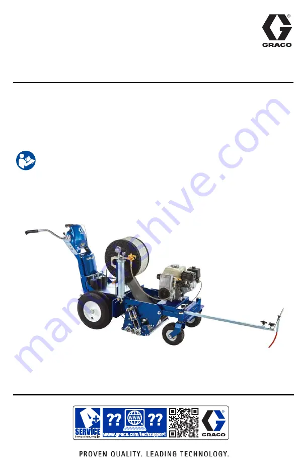
TapeLazer
™
HP Automatic
For application of traffic tape on roads and pavement. For professional use only.
For outdoor use only.
Not approved for use in explosive atmosphere or hazardous (classified) locations.
145 psi (1.0 MPa, 10.0 bar) Maximum Working Pressure
Models: 20A024, 20A140
Important Safety Instructions
Read all warnings and instructions in this manual
and related manuals before using the equipment.
Save these instructions.
Summary of Contents for TapeLazer HP Automatic
Page 15: ...Setup Startup 3A8108A 15 7 Using a 1 4 in Allen wrench tighten bolts ...
Page 25: ...Operation 3A8108A 25 TapeLazer LiveLook Display ...
Page 51: ...Troubleshooting 3A8108A 51 Solenoid Ports Reference ...
Page 52: ...Parts 52 3A8108A Parts TapeLazer Parts ...
Page 54: ...Parts 54 3A8108A Front End Parts ...
Page 56: ...Parts 56 3A8108A Carriage Applicator Parts ...
Page 58: ...Parts 58 3A8108A Display Unit Parts ...
Page 60: ...Parts 60 3A8108A Additional Parts ...
Page 62: ...Air Line Schematic 62 3A8108A Air Line Schematic ...
Page 64: ...Wiring Diagram 64 3A8108A Wiring Diagram ...
Page 65: ...Universal Symbols Key 3A8108A 65 Universal Symbols Key ...


