background image

 3A6748B

EN

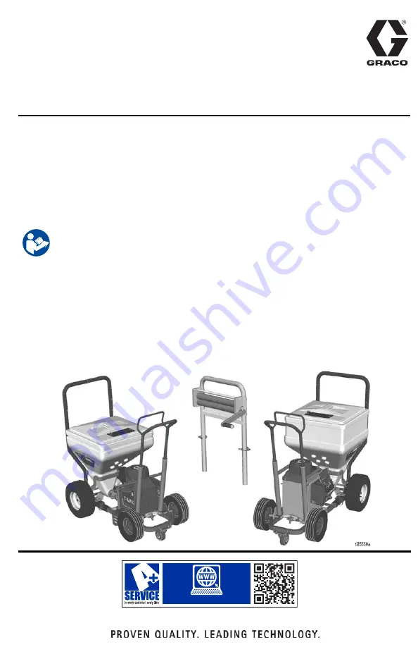
Operation, Repair, Parts

T-Max

 506/657/6912 

Texture Sprayer

For portable spraying of water-based materials. Can be used for application of 
solvent-based materials only when solvent compatible seals are installed and 
solvent compatible, conductive hoses are used. For professional use only.

Not approved for use in European explosive atmosphere locations.
T-Max 506

: 50 bar (5 MPa, 725 psi) Maximum Working Pressure

T-Max 657

: 65 bar (6.5 MPa, 940 psi) Maximum Working Pressure

T-Max 6912: 

69 bar (6.9 MPa, 1000 psi) Maximum Working Pressure

See page 4-6 for model information.

Important Safety Instructions

Read all warnings and instructions in this manual and related manuals before using 

the equipment. Be familiar with the controls and the proper usage of the equipment. 

Save these instructions.

Related Manuals

STX Trigger Gun

3A6746

Bag Roller Kits

312790, 3A4995

T-Max Remote Switch Kit

3A6784

T-Max Applicator

312879

PrimeValve Accessory Kit

3A6785

Free Flow Applicator

313537

Vibra-Flo T-Max

3A6909

Inline Applicator 

309495

Air Manifold Kit

3A6839

www.graco.com/techsupport

??

??

Summary of Contents for T-MAX 506

Page 1: ... 5 MPa 940 psi Maximum Working Pressure T Max 6912 69 bar 6 9 MPa 1000 psi Maximum Working Pressure See page 4 6 for model information Important Safety Instructions Read all warnings and instructions in this manual and related manuals before using the equipment Be familiar with the controls and the proper usage of the equipment Save these instructions Related Manuals STX Trigger Gun 3A6746 Bag Rol...

Page 2: ...e Relief Procedure 19 Setup 21 Start Up Airless 24 Spray Tip Installation 26 Clear Spray Tip Clog 27 Start Up Air Assist 28 Start Up Air Assist STX Gun 30 Operation 32 Cleanup 33 Troubleshooting 39 Repair 43 Control Board Diagnostics 43 Control Board Removal 506 657 45 Control Board Installation 506 657 47 Control Board Removal 6912 49 Control Board Installation 6912 51 Pump Removal 54 Pump Instal...

Page 3: ...06 74 Parts List Pump 74 Parts Pump 289556 657 75 Parts List Pump 75 Parts Pump 25E668 6912 76 Parts List Pump 25E668 6912 77 Parts Control Box 506 657 78 Parts List Control Box 506 657 79 Parts Control Box 6912 80 Parts List Control Box 80 Wiring Diagrams 81 506 657 81 6912 US 82 6912 UK 83 Technical Specifications 84 CALIFORNIA PROPOSITION 65 86 Graco Standard Warranty 87 Graco Information 88 ...

Page 4: ... 110VAC 17X982 3m whip 5m T Max Applicator 17Z291 Bare Unit Multi Cord 230VAC 17X981 3m whip 5m T Max Applicator T MAX 657 Model Hoses Applicator 17 Gallon Hopper Power Cord VAC 17Z171 Bare Unit CEE 7 7 230VAC 17X983 3m whip 5m T Max Applicator 17Z172 Bare Unit UK 110VAC 17X985 3m whip 5m T Max Applicator 17Z292 Bare Unit Multi Cord 230VAC 17X984 3m whip 5m T Max Applicator ...

Page 5: ...m 10m T Max Applicator Free Flow Applicator 17Z288 3m whip 5m 10m T Max Applicator STX Spray Gun 17Z529 3m whip 5m 10m T Max Applicator Pole Applicator 17Z174 Bare Unit UK 110VAC 17Z629 3m whip 5m 10m 17X988 3m whip 5m 10m T Max Applicator 17Z534 3m whip 5m 10m Inline Applicator 17X992 3m whip 5m 10m Free Flow Applicator 17Z282 3m whip 5m 10m STX Spray Gun 17Z287 3m whip 5m 10m T Max Applicator Fr...

Page 6: ...nline Applicator 17X991 3m whip 5m 10m Free Flow Applicator 17X994 3m whip 5m 10m STX Spray Gun 17Z286 3m whip 5m 10m T Max Applicator Free Flow Applicator 17Z289 3m whip 5m 10m T Max Applicator STX SPray Gun 17Z530 3m whip 5m 10m T Max Applicator Pole Applicator 17Z175 Bare Unit NA 120VAC 17Z630 17X989 50 9 whip T Max Applicator 17Z283 50 9 whip STX Spray Gun 17Z284 100 9 whip STX Spray Gun 17Z70...

Page 7: ...en repair or replacement of the cord or plug is required do not connect the grounding wire to either flat blade terminal The wire with insulation having an outer surface that is green with or without yellow stripes is the grounding wire Check with a qualified electrician or serviceman when the grounding instructions are not completely understood or when in doubt as to whether the product is proper...

Page 8: ...ot spray flammable or combustible liquids in a confined area Keep spray area well ventilated Keep a good supply of fresh air moving through the area Sprayer generates sparks Keep pump assembly in a well ventilated area a least 20 feet 6 1 m from the spray area when spraying flushing cleaning or servicing Do not spray pump assembly Do not smoke in the spray area or spray where sparks or flame is pr...

Page 9: ... unattended Follow the Pressure Relief Procedure when the equipment is unattended or not in use and before servicing cleaning or removing parts Check hoses and parts for signs of damage Replace any damaged hoses or parts This system is capable of producing 1000 psi 69 bar 6 9 MPa Use Graco parts or accessories that are rated a minimum of 1000 psi 69 bar 6 9 MPa Verify that all connections are secu...

Page 10: ...ency approvals and create safety hazards Make sure all equipment is rated and approved for the environment in which you are using it Use equipment only for its intended purpose Call your distributor for information Route hoses and cables away from traffic areas sharp edges moving parts and hot surfaces Do not kink or over bend hoses or use hoses to pull equipment Keep children and animals away fro...

Page 11: ...plication only See page14 for all applicators 1 Pump Module 2 Hopper Frame 3 Pump 4 Pump Outlet 5 Pressure Relief Valve 6 Module Securing Clamp 7 Power Cord 8 ON OFF Switch 9 Display 10 Pressure Control Knob 11 Locking Pin 12 Hopper Plug 13 Scraper Tool 14 Whip Hose 15 Material Hose 16 T Max Applicator 17 Inline Applicator 18 Tool Box ...

Page 12: ... application only See page14 for all applicators 1 Pump Module 2 Hopper Frame 3 Pump 4 Pump Outlet 5 Pressure Relief Valve 6 Module Securing Clamp 7 Power Cord 8 ON OFF Switch 9 Display 10 Pressure Control Knob 11 Locking Pins 12 Hopper Plug 13 Scraper Tool 14 Whip Hose 15 Material Hose 16 T Max Applicator 17 Inline Gun 18 Tool Box ...

Page 13: ...for all applicators 1 Pump Module 2 Hopper Frame 3 Pump 4 Pump Outlet 5 Pressure Relief Valve 6 Module Securing Clamp 7 Power Cord 8 Pump Mode Switch 9 ON OFF Switch 10 Amp Switch 11 Display 12 Pressure Control Knob 13 Locking Pins 14 Hopper Plug 15 Signal Air Hose 16 Scraper Tool 17 Material Hose 18 Whip Hose 19 Tool Box 20 Free Flow Applicator 21 STX Spray Gun ...

Page 14: ...t Identification Free Flow Applicator 17Z128 T Max Applicator 17Z054 STX Spray Gun 17Y910 18m Remote Switch 17Z157 30m Remote Switch 17Z158 13m Signal Air Hose 17Z144 18m Signal Air Hose 17Z148 33m Signal Air Hose 17Z151 Inline Applicator 17Y907 ...

Page 15: ...o pump material K Pump Control Setting Description Pressure Mode The motor will run to meet the pressure determined by the Pressure Control Knob K Flow Mode with Remote Control The Flow Mode with Remote Control setting allows the user to control ON OFF functionality of the pump through the remote toggle switch or the STX Spray Gun When the remote toggle switch or the STX Spray Gun is installed and...

Page 16: ...d and the equipment wetted parts Flush at the lowest pressure possible Check connectors for leaks and tighten as necessary 1 Follow Pressure Relief Procedure page 19 2 Set pump to lowest possible fluid pressure and start pump 3 Hold a metal part of the gun firmly to a grounded metal pail Trigger the gun until clean solvent dispenses Amp Switch Select 15A or 20A depending on your circuit rating 110...

Page 17: ...ter based materials only 1 Mix the material and water in a separate container Dry Mix Carefully mix texture material and water according to manufacturer instructions on bag Premix Slowly add water to a 5 gallon 18 9 liter bucket of premix 2 Agitate to mix with mixing paddle to a smooth lump free consistency 3 Make certain all dry powder clumps are mixed throughly before pouring mixture into the sp...

Page 18: ...ut when priming aggregate material NOTE If using other hose lubricants follow manufacturer s mixing instructions 1 Empty one bag of hose lubricant into five gallon bucket and half fill with water 2 Stir for one minute 3 Fill remainder of bucket with water Stir for one minute 4 Let mix stand for at least five minutes or until a slick like texture develops ...

Page 19: ... fully counterclockwise to OFF 2 Point applicator into hopper Turn applicator ON This equipment stays pressurized until pressure is manually relieved To help prevent serious injury from pressurized fluid such as skin injection splashing fluid and moving parts follow the Pressure Relief Procedure when you stop spraying and before cleaning checking or servicing the equipment ...

Page 20: ...e valve down to prime position b VERY SLOWLY loosen the retaining ring hose end coupling or pressure relief valve to relieve pressure gradually c Loosen the retaining nut or the coupling completely d Clear the obstruction in the hose or tip NOTE If pressure relief valve was used to relieve pressure be sure to disassemble and clean thoroughly ...

Page 21: ...r the 6912 longest frame position Depending on materials being sprayed with the T Max 6912 different pump setups might be desired For disassembly instructions see Pump Repair page 60 a Smooth materials Use steel inlet ball with spring and steel outlet ball with spring This is how the unit is shipped b Someaggregates Tohelpprevent packout use a rubber inlet ball with spring and a steel outlet ball ...

Page 22: ...48B c To remove outlet spring remove pump inlet and pump cylinder Then remove spring from the piston 2 Lock front caster 3 Release hopper clamp 4 Move module securing clamp down 5 Connect pump module to hopper frame ...

Page 23: ...er and pump do not align loosen four nuts on back of hopper Make sure hopper and pump are aligned and then tighten four nuts 7 Turn ON OFF Switch to OFF Connect power cord 8 Remove pump plug Connect material hose to pump outlet ...

Page 24: ...fter it has been cleaned or stored 1 Perform Pressure Relief Procedure page 19 2 Fill material hopper with pre mixed texture material Bag roller sold separately 3 Prime pump a Place material hose in hopper b Turn ON OFF Switch to ON c 6912 only Place Pump Mode Switch in up position d Turn Pressure Control Knob clockwise 1 4 turn ...

Page 25: ...al consistency and tip size will determine which filter size to use In certain instances air passage plug with no screen is needed with large tips to successfully spray materials with sand or rock 5 Connect applicator to material hose 6 Turn ON OFF Switch to ON 7 Turn applicator ON Turn Pressure Control Knob clockwise until desired material delivery rate is achieved Run for 15 seconds ti11697a ti8...

Page 26: ...ust be pushed all the way into the tip guard Turn spray tip to push down c Assemble retainingringon tipguard adapter then assemble tip guard 3 Turn the arrow shaped handle on the spray tip forward to the spray position 4 Screw spray tip and tip guard assembly onto the gun and tighten To avoid serious injury from skin injection do not put your hand in front of the spray tip when installing or remov...

Page 27: ... applicator at floor and turn applicator ON When clog clears turn applicator OFF UNCLOG 2 Rotate spray tip back to spray position Turn applicator ON Spray test pattern SPRAY NOTE When spraying if the applicator is not used for a significant period of time be sure to clean the sprayer or keep the gun wet by placing in water or wrapping with a wet cloth This reduces the potential of the material dry...

Page 28: ...f having packout issues in the pump remove the outlet spring and run without it To prime without outlet spring remove hose and pour water into the outlet Place unit in flow mode and turn Pressure Control Knob clockwise until material comes out of the pump outlet Turn pressure control counterclockwise until flow stops then connect material hose If applicable connect a prime valve to the outlet then...

Page 29: ...erial hose in hopper b Turn ON OFF Switch to ON c Place Pump Mode Switch in down position Turn Pressure Control Knob clockwise 1 4 turn d Once a steady stream flows from the material hose run for an additional 30 seconds e Turn ON OFF Switch to OFF ti11697a ...

Page 30: ...pplicator to material hose Connect signal wire connector to gun handle then the air hose 2 Place Pump Mode Switch in center position for remote pump control 3 Holdapplicatorovermaterialhopperand turn applicator ON 4 Turn Pressure Control Knob clockwise until desired material delivery rate is achieved Run 15 seconds ...

Page 31: ... fluid passage 7 Spray test pattern Aim applicator at floor Turn air valve ON Turn applicator ON and move application to spray surface 8 Adjust air needle valve and or select alternative nozzle size 4 12mm for desired finish 9 If a fan pattern is desired remove retaining ring and add adapter housing disk and retaining nut to the assembly 10 Select alternative disk W4 WXL for desired finish ...

Page 32: ...ary hose length decreases sprayer performance Maximum fluid hose lengths T Max 506 15 m of 25 mm ID or 10 m of 25 mm ID 3 m of 19 mm ID T Max 657 30 m of 25 mm ID or 25 m of 25 mm ID 3 m of 19 mm ID NOTE T Max 6912 30 m of 25 mm ID 3m of 19mm ID NOTE Use only one 3 m of 19 mm ID Do not exceed 1000 psi Temperature usage range 0 F 180 F All hoses sent with the unit are for water based material appli...

Page 33: ...ef Procedure page 19 2 Remove applicator Keep applicator wet by placing in water or wrapping with a wet cloth 3 Remove hose and couple ends together 4 Clean hopper sides to material level Cover material in hopper with hopper cover 5 Disconnect pump from hopper ti11732a ti11731a ...

Page 34: ... separately on pump outlet Storage more than 24 hours 1 Perform Pressure Relief Procedure page 19 2 ShutairOFFifsprayingwith air Remove applicator from material hose Clean applicator 3 Turn Pressure Control Knob clockwise and pump unused texture from material hopper and hose ti11711a ti11850a ...

Page 35: ...rom sprayer 5 Rotate pump control to shut pump OFF 6 Disconnect material hose from pump outlet 7 Insert two wet cleaning balls into pump outlet Connect material hose to pump outlet 8 Fill material hopper with water and clean sides 9 RotatePressure ControlKnobclockwise to start pump ...

Page 36: ...otate Pressure Control Knob to shut pump OFF 12 Connect applicator to material hose 13 Turn Pressure Control Knob clockwise to start pump 14 Run pump until clean water flows from applicator Continue until hopper is empty 15 Addadditionalwaterandrepeatsteps13 14 if necessary NOTE After flushing with water flush again with Pump Armor to leave a protective coating to prevent freezing and corrosion ...

Page 37: ...anup 3A6748B 37 16 Rotate Pressure Control Knob to shut pump off 17 Disconnect pump from hopper 18 Flush hopper with water Clean and install drain plug 19 Clean applicators spray tips and guard with brush ...

Page 38: ...A6748B 20 Clean hardened material from applicator nozzles with air nozzle cleaner NOTICE Do not use air nozzle cleaner to clean applicator check valve and spray tip Doing so will damage both items ti11811a ti11847a ...

Page 39: ...plication Up Pressure Mode Middle Remote Control Down Flow Mode Builds pressure but material will not come out Perform Pressure Relief Procedure page 19 Check applicator hose and pump for packout May need to remove outlet spring if packout in pump is reoccuring Basic Mechanical Problems Frozen or hardened paint Thaw sprayer if water or water based paint has frozen in sprayer Placesprayer in warm a...

Page 40: ...se terminals crimp to leads Be sure terminals are firmly connected Clean circuit board terminals Securely reconnect leads ON OFF Switch Connect volt meter between L1 and L2 terminal on ON OFF switch Plug in sprayer and turn ON Meter must read 210 255 Vac for 220 240V models 85 130 Vac for 100 120V models Replace ON OFF switch Check all terminals for damage or loose fit Replace damaged terminals an...

Page 41: ...mance Replace with a correct grounded extension cord Leads from motor to pressure control circuit board for damaged or loose wires or connectors Inspect wiring insulation and terminals for signs of overheating Be sure male terminal blades are centered and firmly connected to female terminals Replace any loose terminal or damaged wiring Securely reconnect terminals Low stall pressure Turn pressure ...

Page 42: ...nals for loose fit or damage Also wires between pressure control and motor Repair or replace any damaged wiring or terminals Securely reconnect all wires Motorarmatureforshorts Inspect windings for burns Replace motor Motorcontrolboardbyperforming motorcontrolboarddiagnostics If diagnostics indicate substitute with a good board Replace with a new motor control board Building circuit breaker opens ...

Page 43: ... 03 Three times repeatedly Sprayer shuts down and LED continues to blink three times repeatedly Pressure transducer is faulty or missing Checktransducerconnection Open drain valve Substitute new transducer fortransducer in sprayer If sprayer runs replace transducer E 04 CODE 04 Four times repeatedly Sprayer does not operate Control board is detecting multiple voltage surges Check voltage switch en...

Page 44: ...y Sprayer does not operate Motor connection problem Set sprayer to OFF and disconnect power to sprayer Remove motor shroud Disconnect motor control and inspect for damge at connectors CODE 16 Sixteen times repeatedly Sprayer does not operate Control is not receiving a motor position signal Turn power OFF Disconnect motor position sensor and inspect for damage at connectors Reconnect sensor Turn po...

Page 45: ... 506 657 1 Perform Pressure Relief Procedure page 19 Unplug power cord to disconnect power 2 Separate pump from hopper 3 Remove four screws and motor cover 4 Remove four screws and control cover Disconnect display from control board ti11854a ...

Page 46: ...screw Disconnectground blue and brown leads 6 Remove power cord from control box 7 Remove filter board screws 8 Remove ON OFF switch toggle boot 9 Disconnect black lead from control board to filter board 10 Remove filter board from control box ti11853a ti11856a ...

Page 47: ...ve grommet E 13 Remove four screws and control board Control Board Installation 506 657 1 Install control board with four screws 2 Connect motor A thermister B potentiometer C and transducer D connectors Install grommet E 3 Install screw through bottom of control box ti11864a 409 ti11862a A B E D C ti11863a ti11863a ti11862a A B E D C ti11864a ...

Page 48: ...nnect black lead from control board to filter board 6 Install ON OFF switch toggle boot 7 Install filter board screw 8 Install power cord C in control box 9 Reference Wiring Diagram page 81 Connect ground blue and brown leads Install screw ti11856a 412 ti11853a ...

Page 49: ...trol board Install control cover with four screws 11 Install motor cover with four screws Control Board Removal 6912 1 Perform Pressure Relief Procedure page 19 Unplug power cord to disconnect power 2 Separate pump from hopper ti11854a ti11737a ...

Page 50: ...Repair 50 3A6748B 3 Remove four screws and motor cover 4 Remove four screws and open cover 5 Remove two screws and remove filter board and amp switch ...

Page 51: ...ducer potentiometer amp switch LED display filter board black blue Remove front cover 7 Disconnect motor leads thermal switch and motor hall encoder sensor Remove grommet 8 Remove two screws from back of control box and remove box Control Board Installation 6912 1 Install control box with two screws ...

Page 52: ... sensor Install grommet 3 Reference Wiring Diagrams page 82 Connect mode switch yellow and black transducer potentiometer amp switch LED display filter board black blue 4 Install filter board in control box with two screws Install amp switch 5 Close cover and install four screws ...

Page 53: ...Repair 3A6748B 53 6 Install motor cover using four screws 7 Connect pump to hopper ...

Page 54: ...ure Relief Procedure page 19 Unplug power cord to disconnect power 2 Perform Storage more than 24 hours procedure page 34 3 Separate pump from hopper 4 Remove four screws and motor cover 5 Remove four screws and control cover ti11854a 506 657 6912 ...

Page 55: ...d strain relief from control box 7 Slowly rotate fan blade on motor until connecting rod is at bottom of stroke 8 Pry retaining spring up on connecting rod toward motor Push pump pin out with a screwdriver 9 Loosen retaining nut 10 Unscrew pump from bearing housing ti11867a ti11747a ...

Page 56: ... from horizontal but no more than one turn 3 Tighten retaining nut 4 Push retaining spring up with a screwdrivertoward motor Push inpump pin Push retaining spring down over pump pin ti11879a 50 70 mm If pump pin loosens parts may break off due to force of pumping action Parts may project through the air and result in serious injury or property damage Make sure pump pin and retaining spring are pro...

Page 57: ...57 5 Install transducer and strain relief in control box Connect transducer to control board 6 Install control cover with four screws 7 Install motor cover with four screws 8 Connect pump module ti11854b 506 657 6912 ...

Page 58: ... Pressure Relief Procedure page 19 Unplug power cord to disconnect power 2 Refer to Pump Removal page 54 to remove pump 3 Remove clamp and intake housing 4 Remove clamp and pump cylinder 5 Remove packing nut Push piston rod from outlet housing 6 Place end of piston rod in vise and remove piston valve 12 Remove piston seal 16 Inspect all parts for nicks and scratches Replace worn or damaged parts a...

Page 59: ...piston rod in vise Install new piston seal Torque piston valve to 27 ft lb 36 6 N m 2 Install packing nut Hand tighten then tap with screw driver Push piston rod into outlet housing Extend piston rod 50 75 mm A out of outlet housing A ti11755a ...

Page 60: ...ump Repair 6912 Disassembly NOTE It may be easier to leave the pump connected to the connecting rod and bearing housing if the only assembies to be cleaned and inspected are the intake housing or piston valve 1 Perform Pressure Relief Procedure page 19 Unplug power cord to disconnect power 2 Refer to Pump Removal page 54 to remove pump 3 Remove clamp and intake housing 4 Disassemble intake valve t...

Page 61: ...e throat packings and glands from cylinder Discard throat packings and glands 7 Place cage of piston rod in vise and remove piston valve Remove piston seal Remove packings and glands from piston rod Inspect all parts for nicks and scratches Replace worn or damaged parts as they may result in poor pump performance ...

Page 62: ...iston valve threads are good for four repackings Use thread sealant on piston valve threads after four repackings Stack male gland on piston rod Alternately stack light and dark packings note orientation page 63 on piston rod Install female gland 2 Install packing nut Hand tighten then tap with screw driver Push piston rod into outlet housing Extend piston rod 50 75 mm A out of outlet housing ...

Page 63: ...Repair 3A6748B 63 Cross Section Reference Pump Ball Identification 6912 ...

Page 64: ...moval page 54 3 Tip unit on back 4 While supporting motor drive housing remove two screws from base 5 Remove four screws washers and bearing housing NOTE Do not drop gear cluster when removing drive housing Gear cluster may stay engaged in motor front end bell or drive housing 6 Remove three screws and drive housing 7 Remove screw and fan ...

Page 65: ...r screws and washers Torque to 25 30 ft lbs 33 9 40 67 N m 3 Install motor with two screws Torque to 200 220 in lbs 22 6 24 9 N m 4 Install fan with screw Torque 11 13 in lb 1 24 1 46 N m 5 Install pump See Pump Installation page 56 NOTICE When installing motor carefully align gears to avoid damaging mating parts ...

Page 66: ... Drain and dispose of fluids according to applicable regulations Refer to the material manufacturer s Safety Data Sheet Dismantle and recycle Remove motors circuit boards LCDs liquid crystal displays and other electronic components Recycle according to applicable regulations Donotdisposeofelectroniccomponents with household or commercial waste Deliver remaining product to a recycling facility ...

Page 67: ...Notes 3A6748B 67 Notes ...

Page 68: ...Parts Hopper Frame 68 3A6748B Parts Hopper Frame b a ...

Page 69: ... 15 100004 SCREW cap hex hd 1 16 104430 PIN cotter 1 17 15C799 ROD clamp 1 18 19A674 BRACKET guide hopper 1 19 113796 SCREW flanged hex hd 4 20 HOPPER material 20a 25E541 17 gallon 1 20b 25E542 25 gallon 1 21 404533 BOLT carriage 4 22 112958 NUT hex flanged 3 8 16 4 23 121313 PIN locking 1 4 2 24 111145 KNOB pronged 2 27 15D306 PLUG adapter hopper 1 30 234188 CLAMP quick release 1 31 19A646 TOOL s...

Page 70: ...Parts Power Module 506 657 70 3A6748B Parts Power Module 506 657 PAGE 78 PAGES 74 75 ...

Page 71: ...painted 1 22 19A670 FRAME left Tmax painted 1 23 107129 BOLT round head 4 35 15D088 FAN motor 1 36 115477 SCREW mach torx pan hd 1 42 19A713 BUMPER rubber 1 43 115483 NUT lock 2 44 103374 SCREw mach rhd 2 45 106062 WHEEL semi pneumatic 2 46 101242 RING retaining 2 47 104811 CAP hub 2 51 100016 WASHER lock 2 52 110298 SCREW cap sch 2 91 15R741 SHIELD Tmax painted 1 92 118444 SCREW mach slot hex was...

Page 72: ...Parts Power Module 6912 72 3A6748B Parts Power Module 6912 PAGE 80 PAGE 76 ...

Page 73: ...3 107129 BOLT round head 4 24 117791 SCREW cap 2 35 15D088 FAN motor 1 36 115U77 SCREW 1 42 19A713 BUMPER rubber 2 43 115483 NUT lock 2 44 103374 SCREW mach 2 45 106062 WHEEL semi pneumatic 2 46 101242 RING retaining 2 47 104811 CAP hub 2 49 19A738 GROMMET 1 91 19A676 COVER motor Tmax painted 1 92 118444 SCREW mach slot hex wash hd 10 93 19A666 SHIELD assy w shroud painted 1 94 15T629 SHIELD pump ...

Page 74: ...7 13 15 16 1 8 248162 SPRING Intake ball 1 9 193395 SEAT carbide 1 10 107098 PACKING o ring 1 11 15R620 ROD pump 1 12 15D112 NUT packing 1 13 501095 SPRING ball check 1 14 121588 O RING 2 15 101822 BALL bearing 1 16 15D116 SEAL piston 1 17 15D115 GUIDE ball 1 18 107167 BALL sst 1 19 248769 HOUSING intake 1 37 111457 O RING 1 38 289672 TRANSDUCER 1 40 17Z238 OUTLET 1 41 17Y930 RELIEF pressure 1 48 ...

Page 75: ...ake ball 1 9 193395 SEAT carbide 1 10 107098 PACKING o ring 1 11 15R620 ROD pump 1 12 15D112 NUT packing 248529 KIT repair throat seal includes 1 2 3 12 1 13 501095 SPRING ball check 1 14 121587 O RING 2 15 101822 BALL bearing 1 16 15D116 SEAL piston 1 17 15D115 GUIDE ball 1 18 107167 BALL sst 1 19 289941 HOUSING intake 1 37 111457 O RING 1 38 289672 TRANSDUCER 1 40 17Z238 OUTLET 1 41 17Y930 RELIE...

Page 76: ...Parts Pump 25E668 6912 76 3A6748B Parts Pump 25E668 6912 ...

Page 77: ...8j 188561 PACKING throat 2 8k 188433 GLAND packing female 1 8m 188558 SEAL u cup 1 8n 188627 WASHER back up 1 8o 17Z242 VALVE piston assy 1 9 19A609 CYLINDER pump 1 10 130792 O RING 2 11 620223 CLAMP 2 12 17Z241 HOUSING intake ball 1 13 235962 SEAL foot valve 1 14 19A692 GUIDE ball inlet 1 15 25E679 SPRING intake assy 1 16 102973 BALL metallic 1 37 111457 O RING 1 38 289672 KIT includes 37 1 40 17...

Page 78: ...Parts Control Box 506 657 78 3A6748B Parts Control Box 506 657 ...

Page 79: ...1 14 24X149 PLATE heat sink 1 15 128038 SCREW mach hex washer hd 2 16 17F671 LABEL control 1 51 100016 WASHER lock 1 52 110298 SCREW CAP sch 1 53 15B120 GROMMET transducer 1 54 121453 CLAMP wire 1 55 15T342 CONDUIT corrugated 1 56a 15B469 CORD st UK 1 56b 158470 CORD st CE 1 57 287789 COVER control 1 58 15G861 LABEL smart control LCD display 1 59 245931 DISPLAY LCD 1 60 115522 SCREW mach pnh 1 61 ...

Page 80: ...REW grounding 1 56 19A642 COVER 1 57 16Y788 LABEL 1 58 17Z406 LABEL 1 59 16X797 LABEL 1 60 120761 COVER jack 1 61 16X796 LABEL 1 62 17D888 POTENTIOMETER 1 63 15C973 GASKET 1 64 116167 KNOB potentiometer 1 65 130863 SWITCH toggle 1 66 19A719 HARNESS 1 67 195428 BOOT toggle 1 68a 15D527 SWITCH rocker 240V 1 68b 15C979 SWITCH rocker 120V 1 69 24U123 BOARD 1 70 114391 SCREW 2 71a 16T544 ADAPTER EU 1 7...

Page 81: ...Wiring Diagrams 3A6748B 81 Wiring Diagrams 506 657 ...

Page 82: ...Wiring Diagrams 82 3A6748B 6912 US ...

Page 83: ...Wiring Diagrams 3A6748B 83 6912 UK ...

Page 84: ...ry with texture material 1 2 to 1 7 gpm 4 5 to 6 4 lpm Fluid outlet size 1 0 in m cam and groove Dimensions Length with handle 42 to 44 in 107 cm to 112 cm Width 23 in 58 cm Height 46 in 117 cm Weight Module only 88 lb 40 kg Module hopper 156 lb 71 kg Noise dBa Maximum sound pressure 82 4 Maximum power level 97 0 Sound pressure measured 3 28 feet 1 meter from equipment Sound power measured per ISO...

Page 85: ...e material 1 4 to 1 9 gpm 5 3 to 7 2 lpm Fluid outlet size 1 0 in m cam and groove Dimensions Length with handle 46 to 48 in 117 cm to 122 cm Width 23 in 58 cm Height 46 in 117 cm Weight Module only 91 lb 41 kg Module hopper 160 lb 73 kg Noise dBa Maximum sound pressure 82 4 Maximum power level 97 0 Sound pressure measured 3 28 feet 1 meter from equipment Sound power measured per ISO 3744 Wetted P...

Page 86: ... handle 46 to 48 in 117 cm to 122 cm Width 23 in 58 cm Height 46 in 117 cm Weight Module only 121 lb 55 kg Module hopper 190 lb 86 kg Noise dBa Maximum sound pressure 80 7 Maximum power level 95 8 Sound pressure measured 3 28 feet 1 meter from equipment Sound power measured per ISO 3744 Wetted Parts Buna N aluminum brass polyethylene neoprene stainless steel chrome plated carbon steel nickel plate...

Page 87: ...s of parts labor and transportation THIS WARRANTY IS EXCLUSIVE AND IS IN LIEU OF ANY OTHER WARRANTIES EXPRESS OR IMPLIED INCLUDING BUT NOT LIMITED TO WARRANTY OF MERCHANTABILITY OR WARRANTY OF FITNESS FOR A PARTICULAR PURPOSE Graco s sole obligation and buyer s sole remedy for any breach of warranty shall be as set forth above The buyer agrees that no other remedy including but not limited to inci...

Page 88: ...polis International Offices Belgium China Japan Korea GRACO INC AND SUBSIDIARIES P O BOX 1441 MINNEAPOLIS MN 55440 1441 USA Copyright 2019 Graco Inc All Graco manufacturing locations are registered to ISO 9001 www graco com Revision B June 2019 Graco Information For the latest information about Graco products visit www graco com For patent information see www graco com patents TO PLACE AN ORDER co...

Reviews: