background image

308–937

Rev. D

Supersedes Rev. A

03228

INSTRUCTIONS-PARTS LIST

INSTRUCTIONS

This manual contains important
warnings and information.
READ AND KEEP FOR REFERENCE.

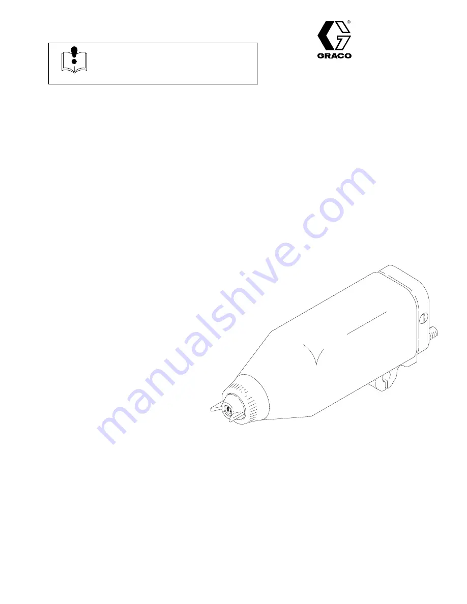
AUTOMATIC ELECTROSTATIC

Model PRO AA5500sc

/UNICARB

Air-Assisted Spray Gun

100 psi (7 bar, 0.7 MPa) Maximum Working Air Pressure
3000 psi (207 bar, 20.7 MPa) Maximum Working Fluid Pressure

For use with Class 

I

, Group D paint spray materials

Part No. 965721, Series B

Complete Spray Gun: includes spray gun, shroud,
manifold, and mounting bracket

U.S. PATENT NO. 4,290,091; 4,219,865; 4,497,447; 4,462,061; 4,660,774; 
5,063,350; 5,080,289; 5,289,977 
Patented 1986, 1987 Canada 
Brevete 1986, 1987 
U.K. PATENT NO. 2,147,158; 2,142,559B; 2,140,327–B 
Other Foreign Patents Pending

UNICARB IS A REGISTERED TRADEMARK OF UNION
CARBIDE, DANBURY CT.

GRACO INC.

P.O. BOX 1441

MINNEAPOLIS, MN

55440–1441

COPYRIGHT 1994, GRACO INC.

Graco Inc. is registered to I.S. EN ISO 9001

Summary of Contents for PRO AA5500SC

Page 1: ...or use with Class I Group D paint spray materials Part No 965721 Series B Complete Spray Gun includes spray gun shroud manifold and mounting bracket U S PATENT NO 4 290 091 4 219 865 4 497 447 4 462 061 4 660 774 5 063 350 5 080 289 5 289 977 Patented 1986 1987 Canada Brevete 1986 1987 U K PATENT NO 2 147 158 2 142 559B 2 140 327 B Other Foreign Patents Pending UNICARB IS A REGISTERED TRADEMARK OF...

Page 2: ...rotection Association NFPA 33 requirements use solvents with a flash point higher than 100 F 38 C or a solvent normally used in spray operations For European Countries complying with EN 50053 use solvents with a flash point as high as possible and higher than the ambient temperatures Use only non sparking tools to clean residue from the booth and hangers Do not flush the system with the gun electr...

Page 3: ...ntly coupled hoses cannot be repaired replace the entire hose INSTRUCTIONS EQUIPMENT MISUSE HAZARD Equipment misuse can cause the equipment to rupture malfunction or start unexpectedly and result in a serious injury This equipment is for professional use only Read all the instruction manuals tags and labels before operating the equipment Use the equipment only for its intended purpose If you are u...

Page 4: ... Fluid Leakage 25 Troubleshooting 26 Spray Pattern Troubleshooting 26 Gun Operation Troubleshooting 27 Electrical Troubleshooting 28 Electrical Tests 29 Test Gun Resistance 29 Test Power Supply Resistance 29 Test Barrel Resistance 30 Service 31 Tools Included with the Gun 31 Prepare the Gun for Service 31 Tip Guard Air Cap Spray Tip or Seat Housing Replacement 33 Electrode Replacement 34 Fluid Tub...

Page 5: ...ack of the manifold through the fitting marked EXH The exhaust air helps keep contaminants out and helps keep the gun clean Switching to the Higher or Lower kV Setting The gun s full high voltage setting is 85 kilovolts The gun s spraying voltage can be reduced by switching to the low voltage setting for spraying in areas where too much electrostatic wrap is not desirable Applying a minimum of 50 ...

Page 6: ...nge color C Tip Guard orange color D Retaining Nut E Shroud F Mounting Bracket G Manifold H Turbine J Power Supply K Electrode Manifold Markings A1 not used A2 Not used CYL Cylinder Air Inlet Fitting EXH Shroud Exhaust Outlet Fitting F O Fiber Optic Fitting KV kV Switch Air Inlet P1 Fluid Supply Inlet Fitting P2 not used TA Turbine Air Inlet Fitting ...

Page 7: ...308937 7 ...

Page 8: ...stance in designing a system that is custom ized for your application contact your Graco distribu tor Warning Signs Mount the warning signs in the spray area where they can easily be seen and read by all operators An English Warning Sign is provided with the gun Addi tional English French German and Spanish signs are available at no charge Part No Description 180060 Warning Sign English 180061 War...

Page 9: ...SYSTEM Fig 1 To FLUID IN P1 at gun K M AA BB S Z U S A R S CC TA CYL W X P1 KV FLUID IN P1 V Q H V Y From coating CO2 supply equipment SYSTEM OPTIONS Spraying Voltage Display Module kV mA kV Non Hazardous Area Hazardous Area 04802 Fig 2 F O EE GG HH KK X JJ FF DD ...

Page 10: ...ury due to component rupture The fluid supply pump must be prevented from producing a fluid pressure greater than the 3000 psi 207 bar 20 7 MPa Maximum Working Pressure of the spray gun For ex ample the air supply pressure to a 30 1 pump must not exceed 100 psi 7 bar 0 7 MPa Be sure that all spray equipment and acces sories added to the spray system are prop erly rated to withstand the maximum wor...

Page 11: ...serious injury including fluid injection and splashing in the eyes or on the skin 2 Install a fluid regulator in the fluid supply system to control fluid pressure to the gun Install the Gun and Mounting Bracket 1 Loosen the mounting bracket s two square head bolts 103 and slide the mounting bracket onto a 0 50 in 12 7 mm mounting rod See Fig 3 2 Position the gun and tighten the two bolts 103 secur...

Page 12: ...3 220119 220120 223068 223069 223070 223071 223072 223073 223074 235068 235069 235070 235071 235072 235073 235074 Black Hose standard hose semi conductive nylon core urethane outer Grey Hose more flexible less durable than black hose modified semi conductive polyamide core urethane cover Red Hose conductive SST wire braid for grounding polyure thane tube and cover Fluid Line Before connecting the ...

Page 13: ...m it is recommended that you install the fiber optic lens kit as described at right NOTE Most of the fiber optic light transmission loss occurs at the bulkhead splices For the strongest light signals use a minimum number of bulkhead splices A maximum of two splices with a total of 108 feet 32 94 m of cable is recommended 5 See manual 308265 to install a Graco ES Display Module Optional Fiber Optic...

Page 14: ...c Air Spray Gun ground the gun by connecting the Graco Electrically Conductive Air Hose to the turbine air inlet and connecting the air hose ground wire to a true earth ground Check the electrical grounding of the gun as instructed on page 15 4 All air and fluid lines must be properly grounded 5 All electric cables must be properly grounded 6 All persons entering the spray area their shoes must ha...

Page 15: ...nd turbine air hose 2 Make sure the turbine air hose B is connected and the hose ground wire is connected to a true earth ground 3 The air and fluid supplies to the gun must be turned off and the fluid hose must not have any fluid in it when checking the continuity 4 Measure the resistance between the turbine air inlet fitting TA and a true earth ground N a If using a black or grey turbine air hos...

Page 16: ...sed tubing and hoses at the back of the manifold See Fig 11 2 Route the exhaust tube YY outside the cover This enables you to monitor the exhaust tube for the presence of any paint or solvent See Check for Fluid Leakage on page 25 Strap down the exhaust tube to prevent it from moving around Fig 11 XX YY YY 03623 03622 Manifold Back View ...

Page 17: ... Checklist WARNING INJECTION HAZARD The wallet sized warning card 179960 provided with the gun should be avail able and easily accessible at all times for anyone operating or servicing this equipment The card contains important information on what to do if a fluid injection injury occurs Additional cards are available at no charge from Graco Check the following list daily before starting to operat...

Page 18: ...s a guide for selection Installing the Pre Orifice WARNING To reduce the risk of a serious injury including fluid injection follow the Pressure Relief Procedure on page 17 when you stop spraying and whenever you are instructed to relieve the pressure 1 Place the spray tip seal 13a on a flat surface See Fig 12 2 Note that the hole through the pre orifice 13b is larger on one side than the other 3 P...

Page 19: ...he system pressure 2 Place the spray tip 13 in the air cap 15 aligning the tab of the tip with the groove in the air cap See Fig 14 Be careful not to bend the electrode wire 15a Fig 14 8800A 13 15 15a 3 Install the spray tip 13 and air cap 15 tip guard 12 shroud 2 and retaining nut 1 onto the gun tighten the retaining nut firmly See Fig 15 WARNING FIRE EXPLOSION AND ELECTRIC SHOCK HAZARD To reduce...

Page 20: ...is used the gun voltage will rise to about 85 kV This will happen with all resistive electrostatic guns See Electrical Troubleshooting on page 28 to cor rect voltage problems Activating the kV Switch Apply a minimum of 50 psi 3 5 bar 0 35 MPa air pressure to the kV switch air fitting KV to activate it and switch to the lower voltage setting The lower voltage setting is factory set to 60 kilovolts ...

Page 21: ...g sprayed Conductive sol vents can cause the gun to malfunction Methylene chloride is not recommended as a flushing or cleaning solvent with this gun as it will damage nylon components Fluid in the air passages could cause the gun to malfunction and could draw current and reduce the electrostatic effect Fluid in the power supply cavity can reduce the alternator life Whenever possible point the gun...

Page 22: ...nd when ever you are done operating the gun WARNING FIRE EXPLOSION AND ELECTRIC SHOCK HAZARD To reduce the risk of a fire explosion or electric shock be sure the turbine air TA is off before flushing the gun or any part of the system Flush the Spray Gun WARNING INJECTION HAZARD To reduce the risk of a serious injury including fluid injection follow the Pres sure Relief Procedure on page 17 when yo...

Page 23: ...he gun with the brush and solvent See Fig 18 Avoid getting any fluid into the air passages Whenever possible point the gun down while cleaning it NOTE If it appears that there is paint inside the air passages remove the gun from the line for servic ing 02007 Fig 18 03233 3 Dampen a soft cloth with solvent and wring out the excess fluid Wipe the exterior of the gun and shroud clean See Fig 19 Fig 1...

Page 24: ...7 Wipe off the parts with a dry cloth Be careful not to bend the electrode wire 8 Check the electrode wire Replace it if it is bent or damaged See page 34 WARNING FIRE EXPLOSION AND ELECTRIC SHOCK HAZARD To reduce the risk of fire explosion and electric shock never operate the spray gun with a bent damaged or missing electrode 15a 9 Place the spray tip 13 in the air cap 15 Align the tab of the tip...

Page 25: ...re on page 17 when you stop spraying and whenever you are instructed to relieve the pressure During operation periodically check the manifold exhaust tube YY and both ends of the gun shroud ZZ for the presence of fluid Fluid in these areas would indicate fluid leakage into the shroud which could be caused by leaks at the fluid tube connections or fluid packing leakage If fluid is seen in any of th...

Page 26: ...ssure or fluid supply is insuf ficient There is air in the fluid supply line The CO2 percentage is fluctuating or is too high The fluid temperature is fluctuating Adjust the flluid CO2 supply system Check tighten the siphon hose connections bleed the air from the fluid line Check fluid CO2 supply system Check temperature control system Irregular pattern There is fluid buildup on the spray tip or t...

Page 27: ... arm not adjusted properly Piston sticking Fluid needle damaged Check Add fluid if necessary Increase cylinder air pressure 65 psi 4 5 bar 0 45 MPa minimum required Clean spray tip and pre orifice See page 23 Check Replace spray tip See page 33 Adjust the actuator arm See page 36 Service piston o rings See page 36 Replace fluid needle See page 39 Equipment covered with fluid Booth exhaust air flow...

Page 28: ...un resistance See page 29 Clean needle cavity Replace fluid needle See page 39 Be sure plug is in place on back of turbine alternator housing Remove and test turbine alternator See page 41 Check switch actuation replace if needed Operator gets shock Operator not properly grounded or is near an ungrounded object Gun not properly grounded Be sure floor is properly grounded Wear shoes with conductive...

Page 29: ...vapors in the area such as open solvent con tainers or fumes from spraying Failure to follow this warning could cause fire explosion electric shock and result in serious injury and property damage Test Gun Resistance See Fig 25 Install the spray tip air cap tip guard and retaining ring on the gun Measure the resistance between the end of the electrode 15a and the gun body 29 or turbine air inlet f...

Page 30: ...tal rod D still inside the barrel as shown in Fig 27 measure the resistance between the wire lead and the metal rod 3 If the resistance is still outside the specified range the gun barrel needs to be replaced If the resistance is correct install a new contact ring 26a and press it firmly into the groove on the front of the barrel Be sure the contact ring is in place before operat ing the gun WARNI...

Page 31: ...n to malfunction which could result in a fire explosion electric shock or injection injury WARNING FIRE EXPLOSION AND ELECTRIC SHOCK HAZARD To reduce the risk of a fire explosion or electric shock Be sure the turbine air TA is off before flushing the gun or any part of the system Clean all the parts with a compatible solvent that is suitable for electro static equipment Do not service this equipme...

Page 32: ...y in the mounting bracket slot A CAUTION The piston return spring 105 is compressed between the manifold 101 and gun body when they are assembled To avoid sudden movement of the gun loosen the bottom gun screw 21 before loos ening the three manifold bolts 106 This allows the gun to move forward gradually as the manifold bolts are loosened Hold the gun firmly in hand while loosening the manifold bo...

Page 33: ...eplace it and never operate the gun without the contact ring in place Do not replace the contact ring with anything but a genuine Graco part 4 Install the seat housing 14 with the 9 mm driver 84 Tighten the seat housing until it s snug and then tighten it 1 4 turn more do not over tighten CAUTION To avoid damaging the seat housing and gun barrel never over tighten the seat housing Over tightening ...

Page 34: ...perate the spray gun with a bent damaged or missing electrode 15a 1 Prepare the gun for service as instructed on page 31 2 Remove the retaining nut 1 tip guard 12 air cap 15 spray tip 13 and gun shroud 2 as instructed on page 33 3 Pull the electrode 15a out of the backside of the air cap with a needle nose pliers Refer to Fig 31 4 Push the new electrode 15a through the air cap hole Place firm fing...

Page 35: ...sure the top fluid tube nut L remains tightened 8 Install the shroud 2 spray tip 13 air cap 15 tip guard 12 and retaining nut 1 as instructed on page 34 Tighten the retaining nut firmly 9 Test the gun resistance as instructed on page 29 10 Install the gun onto the manifold and bracket as instructed on page 43 Fluid Filter Replacement 1 Prepare the gun for service as instructed on page 31 2 Disconn...

Page 36: ...le than the adjustment nut 17 a Thread the jam nut 8 flush with the end of the piston rod 23g Tighten the adjustment nut 17 against the actuator arm 19 When properly assembled there should be about a 0 125 in 3 mm gap between the actuator arm 19 and the fluid packing rod nut U which allows the atomizing air to actuate before the fluid actuates See Fig 36 8 Install the shroud 2 spray tip 13 air cap...

Page 37: ...Air Seal It is the air shut off seal If the air leaks from the air cap when the gun is detrig gered replace these o rings O Ring 23c Back Air Seal It separates the cylinder air pressure from the atomizing air pressure U cup 23f Cylinder Air Seal If the air leaks from the small vent hole in the back of the manifold when the gun is triggered replace the u cup Fig 38 23a 23c 23b 23f 03531 ...

Page 38: ...with the ball end wrench 77 See Fig 40 5 Hold the gun body 29 with one hand and pull the barrel 26 straight away from the body to remove it See Fig 41 CAUTION To avoid damaging the power supply 27 pull the gun barrel straight away from the gun body If neces sary gently move the barrel from side to side to free the power supply from the gun body 03628 Fig 39 26 29 C 8 19 Fig 40 24 77 03238 Fig 41 2...

Page 39: ...4 supplied See Fig 30 page 33 3 Remove the barrel as instructed on page 38 4 Place the 2 mm driver 79 in the back of the fluid needle assembly 28 See Fig 42 Push the tool in and turn it counterclockwise about 12 full turns to unthread the needle 5 Insert the 2 mm driver 79 into the front of the gun and push the fluid needle assembly 28 out the back of the gun body CAUTION To avoid damaging the flu...

Page 40: ...y replace the power supply 5 Before installing the power supply inspect the seal 27d for any damage or swelling replace the seal if necessary Make sure the gaskets and pads 27a 27e are in place 6 Lubricate the o ring 25a and install the power supply in the gun body 7 Assemble the gun as instructed on page 42 Lower Voltage Setting Adjustment The kV switch in the manifold enables you to switch betwe...

Page 41: ...arefully pull the alternator 25 away from the power supply 27 until the wire connector V disengages See Fig 44 4 Use an ohmmeter to test the turbine alternator coil Measure the resistance between the two outer terminals of the 3 wire connector V Resistance should be 3 to 5 ohms If the reading varies from this value replace the alternator 5 Connect the 3 wire connector to the 3 prongs in the power ...

Page 42: ...er tighten the screws 24 4 Make sure the fluid filter 4 is in place then tighten the bottom fluid tube nut C onto the fluid fitting 3 make sure the top fluid tube nut D remains tightened 5 Install and adjust the actuator arm 19 and jam nut 8 onto the piston rod 23g as instructed on page 36 6 Install the shroud 2 spray tip 13 air cap 15 tip guard 12 and retaining nut 1 as instructed on page 33 Tigh...

Page 43: ...ht ening the three screws 106 with the ball end wrench 77 not shown 4 Connect the fluid hose to the fluid inlet fitting 3 marked P1 on the manifold Use an open end wrench to hold the fluid fitting hex and prevent it from turning 5 Secure the gun B to the mounting bracket 102 by tightening the screw 21 with the ball end wrench 77 6 Slide the shroud 2 over the gun 7 Install the spray tip 13 air cap ...

Page 44: ... page 47 to order parts Item 23 includes 23a 23g Item 25 includes 25a 25b Item 27 includes 27a 27e 28 11 27c 30 25b 25 25a 27 27d 27a 27e 27b 12 2 15 15a 13 13a 14 26a 26 24 REF 18 6 7 20 19 8 17 18 4 3 21 10 29 23a 23g 23b 23c 23d 23f 23e 13b ...

Page 45: ... compression Included with item 28 1 21 112689 SCREW socket 1 4 x 0 75 1 Ref No Part No Description Qty 23 236826 PISTON ASSY Includes items 23a 23g 1 23a 111508 O RING fluoroelastomer 1 23b 111504 O RING fluoroelastomer 2 23c 112319 O RING fluoroelastomer 2 23d 189355 STEM piston 2 23e 189747 PISTON 1 23f 189752 PACKING u cup UHMW polyethylene 1 23g 189754 ROD piston 1 24 185096 SCREW cap relieve...

Page 46: ...ress fit the spring 105 Tighten the fitting until the hex bottoms against the manifold This fitting 113 has left hand threads Install the kV cap 111 flush to the outside surface Concave side of the disk 114 faces toward the manifold Replace the spring 122 every 300 000 cycles An optional fiber optic fitting 37 is included with the gun assembly see page 45 Remove the plug 115 and install the fittin...

Page 47: ...anifold 1 109 108290 SCREW 8 32 x 1 4 2 110 236696 kV SWITCH 1 111 189365 kV CAP 1 112 110078 FITTING tube for 3 8 OD tube 1 113 186845 FITTING turbine 1 4 18 npsm left hand thread 1 114 107107 REGULATOR disk 1 115 112645 PLUG 1 8 27 npt 1 116 112646 PLUG 5 8 18 x 5 8 1 119 112678 PLUG 1 4 npt 1 121 190301 GASKET foam 1 122 112641 SPRING 1 123 111316 O RING fluoroelastomer 1 These parts are includ...

Page 48: ...MPa Maximum Working Pressure For turning air to gun off or on 1 4 npsm m x 1 4 npsm f left hand thread Bleed type Master Air Valve 107141 300 psi 21 bar 2 1 MPa Maximum Working Pressure Relieves air trapped in the air line between the paint pump air motor and this valve when closed 3 4 npt FLUID LINE ACCESSORIES Nylon Static Free Fluid Hoses 3300 psi 228 bar 22 8 MPa Maximum Working Pressure Part ...

Page 49: ...ÎÎÎÎÎ ÎÎÎÎÎ ÎÎÎÎÎ ÎÎÎÎÎ ÎÎÎÎÎ 0309 24 Volt Power Supply 235301 Provides 24 volt power for up to 23 ES Display Mod ules 01339 CABLE ACCESSORIES Fiber Optic Cable Assembly For connection between gun manifold and display module or between bulkhead connector and display module PART NO LENGTH 224680 6 ft 1 8 m 224681 15 ft 5 m 224682 25 ft 8 m 224683 36 ft 11 m 224684 50 ft 15 m 224685 75 ft 23 m 22468...

Page 50: ...as Gun High Voltage Probe and Meter 236003 For direct measurement of gun output voltage Paint Resistance Meter 722886 Used with 722860 Paint Probe to measure resistance of paint Not for use in Hazardous areas Paint Probe 722860 Used with 722886 Paint Resistance Meter to measure resistance of paint Not for use in Hazardous areas Safety Warning Signs Available at no charge from Graco 180060 Warning ...

Page 51: ...2 GG3317 6 8 150 200 GG3417 8 10 200 250 GG3517 10 12 250 300 GG3617 12 14 300 350 Part No Fan Width at 10 in 260 mm in mm Orifice Size in mm GG3319 6 8 150 200 0 019 0 483 GG3419 8 10 200 250 GG3519 10 12 250 300 GG3619 12 14 300 350 GG3719 14 16 350 400 GG3421 8 10 200 250 0 021 0 533 GG3521 10 12 250 300 GG3621 12 14 300 350 GG3721 14 16 350 400 GG3821 16 18 400 450 GG3423 8 10 200 250 0 023 0 ...

Page 52: ...urrent Output 120 µA Paint Resistivity Range 3 megohm cm to infinity Category Data Maximum Fluid Temperature 120 F 49 C Turbine Air Inlet 1 4 npsm m left hand Fluid Inlet 1 4 npsm m Wetted Parts Stainless Steel Nylon PEEK Ultra High Molecular Weight Polyethylene Tungsten Carbide Sound pressure was measured per Cagi Pneurop 1969 The measurement was taken 3 28 feet 1 meter from the air cap Sound pow...

Page 53: ...308937 53 Notes ...

Page 54: ...ment does not disclose any defect in material or workmanship repairs will be made at a reasonable charge which charges may include the costs of parts labor and transportation DISCLAIMERS AND LIMITATIONS The terms of this warranty constitute purchaser s sole and exclusive remedy and are in lieu of any other warranties express or im plied including warranty of merchantability or warranty of fitness ...

Reviews: