Automatic Electrostatic Gun for use in Class I, Div. I Hazardous Locations using Group D
spray materials.
Automatic Electrostatic Gun for use in Group II, Zone 1 Explosive Atmosphere Locations
using Group IIA spray materials.
For professional use only.
100 psi (0.7 MPa, 7 bar) Maximum Air Inlet Press
3000 psi (21 MPa, 210 bar) Maximum Working Fluid Pressure
Important Safety Instructions
Read all warnings and instructions in this manual
and in related manuals. Save these instructions.
See page 2 for
Table of Contents
and page 3 for
List of Models
.
WLD
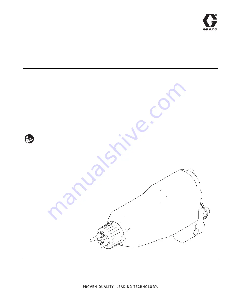
Instructions-Parts
Pro Xp
™
Auto AA Spray Gun
333011D
EN