background image

333208F

EN

Operation-Repair-Parts

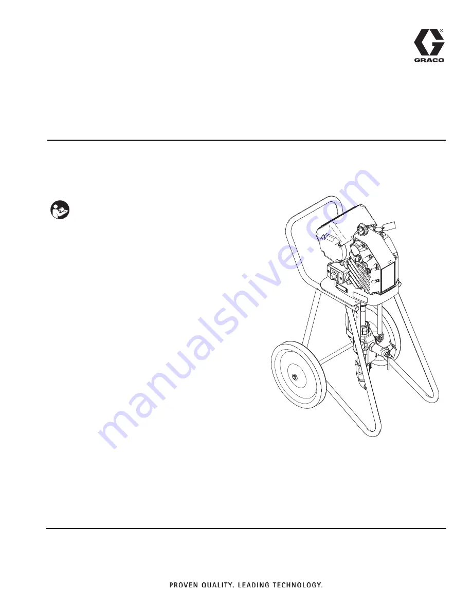
Electric High Pressure 

Airless Sprayer

Electric high pressure sprayer packages for application of protective coatings. 
For professional use only. 
Not approved for use in explosive atmospheres or hazardous locations.

For 

Model Information

 and maximum working pressure, 

see page 2.

Important Safety Instructions

Read all warnings and instructions in this 
manual. Save these instructions. 

WLE

Summary of Contents for e-Xtreme Z25

Page 1: ...ages for application of protective coatings For professional use only Not approved for use in explosive atmospheres or hazardous locations For Model Information and maximum working pressure see page 2 Important Safety Instructions Read all warnings and instructions in this manual Save these instructions WL E ...

Page 2: ...ensions 25 Technical Specifications 26 California Proposition 65 27 Graco Standard Warranty 28 Model Information Lower fluid temperature due to XTR5 gun Related Manuals Manuals are available at www graco com Model Description Maximum Working Pressure Maximum Fluid Temperature Approvals 24X450 Includes hose and gun 4500 psi 31 MPa 310 bar 160 F 71 C 24X451 No hose or gun 4500 psi 31 MPa 310 bar 180...

Page 3: ...Do not expose to rain Store indoors BURN HAZARD Equipment surfaces and fluid that is heated can become very hot during operation To avoid severe burns Do not touch hot fluid or equipment FIRE AND EXPLOSION HAZARD Flammable fumes such as solvent and paint fumes in work area can ignite or explode To help prevent fire and explosion Use equipment only in well ventilated area Eliminate all ignition sou...

Page 4: ...in all equip ment manuals Read fluid and solvent manufacturer s warnings For complete information about your material request MSDS from distributor or retailer Do not leave the work area while equipment is energized or under pressure Turn off all equipment and follow the Pressure Relief Procedure when equipment is not in use Check equipment daily Repair or replace worn or damaged parts immediately...

Page 5: ...ount A Electric Driver B Lower C Fluid Drain Purge Valve D Packing Nut E Power Switch F Fluid Outlet G Junction Box Cover H Pressure Adjustment Knob I Outlet Check Valve L Red Indicator Light P Oil Fill Cap Vented S Junction Box FIG 1 Airless Sprayer WL E D A C F E G H I B L S P ...

Page 6: ...ls See FIG 4 For Series A and B terminals 1L1 and 3L2 For Series C terminals 1L1 and 5L3 NOTE Press gasket against back sealing face of junction box cover to ease installation of power cord 4 Insert power cord from step 1 through cord grip C2 and into junction box S NOTE Power wires should be installed into terminals See FIG 4 Series A and B terminals 2T1 and 4T2 Series C terminals 2T1 and 6T3 Imp...

Page 7: ...ther side of disconnect block J as space permits Reinstall junction box cover See FIG 5 7 Replace junction box screws and washers removed in step 2 and tighten cord grip to securely hold power cord in junction box S See FIG 6 NOTICE If wires get pinched when the screws are tightened damage will occur Make sure all wires are routed correctly before installation FIG 5 Grounding Wire WL E WL D G E J ...

Page 8: ...ld metal part of the spray gun dispense valve firmly to the side of a grounded metal pail then trigger the gun valve Install Vented Oil Cap Before Using Equipment The driver gear box is shipped from the factory prefilled with oil The temporary unvented cap PX prevents oil leaks during shipment This temporary cap must be replaced with the vented oil cap P supplied with equipment before use Flush Be...

Page 9: ...knob in to lock 6 Turn power switch E OFF Connect unit to power source See FIG 3 page 6 7 Always flush and prime sprayer before each use see page 11 To avoid tip over make sure cart is on a flat and level surface Failure to do so could result in injury or equipment damage NOTICE Attaching the hose directly to the lower pump can result in damage to the sprayer during cavitation or when the sprayer ...

Page 10: ...that pressure has not been fully relieved after following the previous steps VERY SLOWLY loosen the tip guard retaining nut or hose end coupling and relieve pressure gradually then loosen completely With tip removed trigger gun into bucket Trigger Lock Always engage the trigger lock when you stop spraying to prevent the gun from being triggered accidentally by hand or if dropped or bumped This equ...

Page 11: ...ipment is now ready to spray proceed to Spray page 12 If flushing proceed with step 8 NOTE The remaining steps are for flushing only 8 Place drain tube in a grounded waste pail 9 Slightly rotate drain purge valve handle C counterclockwise to open 10 To start pump pull out pressure adjustment knob H and turn clockwise until pump begins to move Push knob in to lock 11 When clean solvent flows from d...

Page 12: ... recommendations Adjust as necessary 8 Flush when finished spraying See Prime Flush page 11 9 Perform Pressure Relief Procedure page 10 Shutdown To shutdown perform Prime Flush procedure page 11 Perform Pressure Relief Procedure page 10 NOTICE Do not allow pump to run dry It will quickly accelerate to a high speed causing damage WL E 21 E H ti20171a_1 _ NOTICE Never leave water or water based flui...

Page 13: ...ump at bottom of its stroke to prevent fluid from drying on exposed displacement rod and damaging throat packings Perform Pressure Relief Procedure page 10 1 Perform Flush procedure page 11 2 Relieve pressure See Pressure Relief Procedure page 10 3 Check packing nut D See FIG 1 page 5 Adjust packings and replace TSL as necessary Torque to 25 ft lb 34 N m 4 Check hoses tubes and couplings Tighten a...

Page 14: ... from corrosion Flushing Flush before changing fluids before fluid can dry in the equipment at the end of the day before storing and before repairing equipment Flush at the lowest pressure possible Check connectors for leaks and tighten as necessary Flush with a fluid that is compatible with the fluid being dispensed and the equipment wetted parts Cart Maintenance Periodically lubricate the axle b...

Page 15: ...up filled with compatible solvent Driver parts are worn or damaged Repair or replace driver No pressure Fluid leaking from rupture disk Replace rupture disk with new one do not replace with pipe plug Leaking drain valve Close or replace Driver does not turn on fans may still run Over voltage over 300 V See Power Supply page 6 No power to control board Verify power supply is connected Check junctio...

Page 16: ...y No power to control board Contact your Graco distributor or Tech Service for more information Driver does not turn over and LED is on Encoder fault Cycle power Recalibrate the encoder following the procedure listed in the Electric Driver Manual 333233 Contact your Graco distributor or Tech Service for more information Oil is leaking Oil was over filled Drain and refill as stated in Check Oil Lev...

Page 17: ...rized but the pump has not moved any material in 30 minutes the sprayer will enter Power Saving Mode and will only control up to 75 of the maximum pressure Power Saving Mode will be exited when Material starts to dispense and causes the pump to move OR The pressure knob is adjusted OR Power is cycled OFF and ON WL D Blink Code Error Type Troubleshooting Steps 1 Alarm Voltage Too Low Verify that li...

Page 18: ...ibrate the encoder see driver manual Contact your Graco distributor or Tech Service for more information 8 Alarm Encoder Error Cycle power and check the status indicator to see if the error is still active Verify that the encoder cable is connected securely The encoder may need to be replaced Contact your Graco distributor or Tech Service for more information 9 Alarm Software Versions Do Not Match...

Page 19: ...er does not require service leave it attached to its mounting To prevent skin injection and splashing never open a camlock hose or applicator fitting while there is pres sure in the fluid line Perform Pressure Relief Proce dure page 10 before performing any repair procedure The material and equipment may be hot To avoid burns do not touch hot fluid or equipment Wait until equipment has cooled comp...

Page 20: ...2 7 Use a wrench to hold tie rod flats to keep rods 8 from turning Unscrew nuts 10 and remove lower 9 8 Refer to Xtreme Lower manual 311762 to service lower 9 Reconnect lower by following disconnect steps in reverse order NOTE Torque nuts 10 to 50 60 ft lb 68 81 N m 11 13 12 WL E 9 10 8 ...

Page 21: ...from the valve housing 8 Remove and clean all internal outlet check valve components Inspect all components for wear or damage and replace components as needed 9 Reassemble parts in the reverse order they were removed ball guides 3 spring retainer compression spring and ball Use a small blunt tool to push the ball in and verify that the ball and spring move freely 10 Replace the o ring and coat wi...

Page 22: ... 3 1 6 14 1 49 7 8 24 25 47 46 45 44 2 3 5 11 13 12 9 15 10 52 58 55 64 2 23 17 56 67 66 65 105 107 107 106 Models 24Y452 24Y317 25A829 Models 24X450 24Y452 24W315 24Y317 only Models 24W315 24W316 24Y317 71 64 25A829 only 108 69 48 31 4 ...

Page 23: ... 46 H42506 HOSE cpld 4500 psi 25 ID 6 ft Models 24X451 24W316 24Y317 24Y452 1 47 XTR510 GUN XTR5 1 in HND 4fng XHD529 nf Models 24X451 24W316 24Y317 24Y452 1 48 XHD651 TIP spray high output Models 24W315 24Y317 1 49 15H525 CAP fill 1 52 17B507 COVER junction box 1 55 VALVE outlet check 1 56 17B509 GASKET cover junction box 1 57 TAG oil 1 58 17A411 LABEL instructions 1 64 162505 FITTING union swive...

Page 24: ...3 4 102972 BALL metallic 1 5 17A091 HOUSING ball check 1 6 181535 RETAINER spring 1 7 108361 SPRING compression 1 23 245143 VALVE pressure bleed 1 If the outlet check valve is disassembled the o ring 2 must be replaced The o ring is designed to be crushed and not reused Ref Instruction Torque to 101 108 N m 75 80 ft lb Apply lubricant Part Description 17B291 MIXER jiffy PS 1 24V083 HOPPER KIT 24V4...

Page 25: ...Dimensions 333208F 25 Dimensions Driver Dimensions A height 50 0 in 1 27 m B depth 33 5 in 0 85 m C width 28 0 in 0 71 m WL D A B C ...

Page 26: ...Y317 Carbon Steel Alloy Steel 304 440 and 17 PH Grades of Stainless Steel Zinc and Nickel Plating Ductile Iron Tungsten Carbide PTFE Leather Aluminum Model 25A829 Carbon Steel Alloy Steel 304 440 and 17 PH Grades of Stainless Steel Zinc and Nickel Plating Ductile Iron Tungsten Carbide PTFE Aluminum Ambient operating temperature range 23 to 120 F 5 to 50 C Maximum fluid temperature See Model Inform...

Page 27: ...California Proposition 65 333208F 27 California Proposition 65 CALIFORNIA RESIDENTS WARNING Cancer and reproductive harm www P65warnings ca gov ...

Page 28: ... material or workmanship repairs will be made at a reasonable charge which charges may include the costs of parts labor and transportation THIS WARRANTY IS EXCLUSIVE AND IS IN LIEU OF ANY OTHER WARRANTIES EXPRESS OR IMPLIED INCLUDING BUT NOT LIMITED TO WARRANTY OF MERCHANTABILITY OR WARRANTY OF FITNESS FOR A PARTICULAR PURPOSE Graco s sole obligation and buyer s sole remedy for any breach of warra...

Reviews: