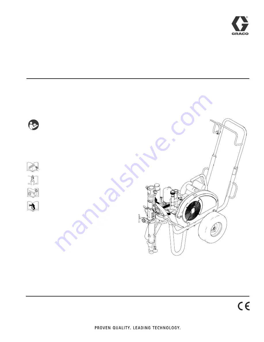
background image

Repair

DutyMax

 Hydraulic Sprayers

3A2247A

EN

-


For professional use only -

- Not approved for use in European explosive atmosphere locations -

Models: 24M054 (EH200DI), 24M055 (GH200DI), 24M056 (EH300DI), 24M057 (GH300DI)

3300 psi (22.8 MPa, 228 bar) Maximum Working Pressure

See page 3 for model information.

Important Safety Instructions

Read all warnings and instructions in this 
manual. Save these instructions.

3A2246

311845

3A2248

308491 - Blue Texture Gun
309495 - Inline Texture Gun

ti18188a

Summary of Contents for DutyMax 24M054

Page 1: ... Models 24M054 EH200DI 24M055 GH200DI 24M056 EH300DI 24M057 GH300DI 3300 psi 22 8 MPa 228 bar Maximum Working Pressure See page 3 for model information Important Safety Instructions Read all warnings and instructions in this manual Save these instructions 3A2246 311845 3A2248 308491 Blue Texture Gun 309495 Inline Texture Gun ti18188a ...

Page 2: ...tion 14 Electric Motor Starter 15 Removal 15 Installation 16 Electric Motor 18 Removal 18 Installation 20 Hydraulic Motor Rebuild 23 Removal 23 Installation 23 Hydraulic Motor 24 Hydraulic Oil Filter Change 25 Removal 25 Installation 25 Displacement Pump 26 Removal 26 Installation 27 Check Valve Repair 28 Removal 28 Installation 28 Wiring Diagram 29 Notes 30 Technical Data 31 Graco Standard Warran...

Page 3: ...Phase EH300DI CSA 400VAC 50 Hz 3 Phase BLUE GUN 1 4 in x 3 ft WHIP 3 8 in x 50 ft HOSE INLINE GUN 3 8 in x 12 in WHIP 1 2 in x 50 ft HOSE Kit Number Sprayer Model Description 24M666 EH200DI Gas Conversion Kit 24M667 EH300DI Gas Conversion Kit 24M668 GH200DI Electric Conversion Kit 24M669 GH300DI Electric Conversion Kit ...

Page 4: ...s manual where applicable DANGER HIGH VOLTAGE ELECTRIC SHOCK HAZARD This equipment uses high voltage power Improper contact with high voltage equipment will cause death or serious injury Turn off and disconnect power cord before servicing equipment This equipment must be grounded Connect only to grounded power source Use only 3 wire extension cords for 240V and single phase models Use only 5 wire ...

Page 5: ...rson or animal Keep hands and other body parts away from the discharge For example do not try to stop leaks with any part of the body Always use the nozzle tip guard Do not spray without nozzle tip guard in place Use Graco nozzle tips Use caution when cleaning and changing nozzle tips In the case where the nozzle tip clogs while spraying follow the Pressure Relief Procedure for turning off the uni...

Page 6: ... replacement parts only Do not alter or modify equipment Alterations or modifications may void agency approvals and create safety hazards Make sure all equipment is rated and approved for the environment in which you are using it Use equipment only for its intended purpose Call your distributor for information Route hoses and cables away from traffic areas sharp edges moving parts and hot surfaces...

Page 7: ...D Equipment surfaces and fluid that s heated can become very hot during operation To avoid severe burns Do not touch hot fluid or equipment PERSONAL PROTECTIVE EQUIPMENT Wear appropriate protective equipment when in the work area to help prevent serious injury including eye injury hearing loss inhalation of toxic fumes and burns This protective equipment includes but is not lim ited to Protective ...

Page 8: ...uch fitting 2 Lubricate o ring A 3 Screw in fitting hand tight 4 Unscrew fitting until oriented properly 5 Tighten lock nut to indicated torque Make sure washer is seated properly without pinching o ring DA HIGH VOLTAGE ELECTRIC SHOCK HAZARD This equipment uses high voltage power Improper contact with high voltage equipment will cause death or serious injury Turn off and disconnect power cord befo...

Page 9: ...t DAILY Check level of Throat Seal Liquid TSL in dis placement pump packing nut Fill nut if necessary Keep TSL in nut to help prevent fluid buildup on piston rod and premature wear of packings and pump corrosion WEEKLY DAILY Remove any debris or media from hydraulic rod AFTER EACH 100 HOURS OF OPERATION Change engine oil see Honda engine owner s manual for correct oil viscosity SEMI ANNUALLY Check...

Page 10: ...ing the EH300DI 24M056 sprayer the generator must be sized for 15 kW output minimum Incorrect amp setting on motor starter 3 phase motor only Have a certified electrician or authorized Graco Repair Center evaluate and repair See Technical Data page 30 Over current switch has tripped Have a certified electrician or authorized Graco Repair Center evaluate and repair See Technical Data page 30 Hydrau...

Page 11: ...ing nut or replace packings See manual 311845 Intake valve ball check not seating properly Service intake valve ball check See manual 311845 Displacement pump air leak Paint leaks and runs over side of wetcup Loosen wet cup Tighten wet cup enough to stop leakage Throat packings worn or damaged Replace packings See manual 311845 Excessive leakage around hydraulic motor piston rod wiper Piston rod s...

Page 12: ...5 Raise electric motor or gas engine and remove belt 44 6 Remove two set screws 197 and fan pulley 96 7 Remove case drain tube 225 8 Remove elbow 221 This equipment stays pressurized until pressure is manually relieved To help prevent serious injury from pressurized fluid such as skin injection splashing fluid and moving parts follow the Pressure Relief Procedure when you stop spraying and before ...

Page 13: ...over 209 4 Install elbow 226 in hydraulic pump 220 Install hose 276 in elbow 226 Torque to 15 ft lb 20 3 N m 5 Install elbow 221 torque to 15 ft lb 20 3 N m 6 Install case drain tube 225 torque to 15 ft lb 20 3 N m 7 Install fan pulley 96 with two set screws 197 8 Raise electric motor or gas engine and install belt 44 9 Install belt guard 117 with screw 172 and nut 173 10 Install drain plug 202 In...

Page 14: ...wn to put tension on belt 3 Rotate belt guard 117 down 4 Tighten belt guard knob 55 This equipment stays pressurized until pressure is manually relieved To help prevent serious injury from pressurized fluid such as skin injection splashing fluid and moving parts follow the Pressure Relief Proce dure when you stop spraying and before cleaning checking or servicing the equipment ti18342a 117 44 119 ...

Page 15: ...nly to grounded power source Use only 3 wire extension cords for 240V and single phase models Use only 5 wire extension cords for 400 AC and three phase models Ensure ground prongs are intact on power and extension cords Do not expose to rain Store indoors All electrical wiring must be done by a qualified electrician and comply with all local codes and regulations This equipment stays pressurized ...

Page 16: ...rews 200 from motor mounting bracket 195 9 Remove motor starter assembly 198 Installation 3 Phase 400 VAC 50 Hz Electric Motor Starter 1 Install motor starter 198 on motor starter bracket 195 2 Install six screws 200 into motor starter 198 Torque screws to 20 in lb 2 3 N m 3 Remove motor junction box cover J 4 Remove strain relief fitting S from motor junction box cover J 5 Slide strain relief fit...

Page 17: ...Install motor junction box cover J to motor junction box Torque junction box cover to 28 in lb 3 2 N m 9 Install motor assembly on sprayer 10 Swing electric motor retainer bracket 204 in Tighten electric motor nut 205 11 Install Fan Belt page 14 12 Check to make sure fan pulley and motor pulley are in line Also check to make sure fan pulley shaft and motor pulley shaft are parallel Adjust as requi...

Page 18: ...t power cord before servicing equipment This equipment must be grounded Connect only to grounded power source Use only 3 wire extension cords for 240V and single phase models Use only 5 wire extension cords for 400 AC and three phase models Ensure ground prongs are intact on power and extension cords Do not expose to rain Store indoors All electrical wiring must be done by a qualified electrician ...

Page 19: ...rown black and grey wires and the yellow and green ground wire see Wiring Diagram page 29 7 Remove cable strain relief fitting S from motor junction cover and pull motor power lead 3 and motor ground wire from motor junction cover 8 Remove four screws 30 nuts 174 and handle 175 from motor mounting bracket 99 9 Remove four screws 23 nuts 174 and electric motor 119 from motor mounting bracket 99 10 ...

Page 20: ... on rocker plate Torque screws 30 to 225 in lb 25 4 N m 3 Install motor assembly on sprayer 4 Swing electric motor retainer bracket 204 in Tighten electric motor nut 205 5 Install Fan Belt page 14 6 Check to make sure fan pulley and motor pulley are in line Also check to make sure fan pulley shaft and motor pulley shaft are parallel Adjust as required 119 204 99 193 191 192 174 190 175 30 133 43 2...

Page 21: ...on box cover J 8 Be sure gasket is in position on motor junction box cover Connect three power leads and ground Con nect yellow and green ground wire to motor junction box ground connection Connect power leads as fol lows Brown wire to motor terminal U1 Black wire to motor terminal V1 Grey wire to motor terminal W1 See Wiring Diagram page 29 for connection locations Torque power leads to 28 in lb ...

Page 22: ...all Fan Belt page 14 13 Check to make sure fan pulley and motor pulley are in line Also check to make sure fan pulley shaft and motor pulley shaft are parallel Adjust as required ti5387a ti18705a Motor Pulley 133 FLUSH Motor pulley to Motor Shaft Parallel Fan Pulley Shaft Fan Pulley 43 In Line end of motor shaft ...

Page 23: ...draulic motor cap 268 to 150 ft lb 17 N m 4 Install hydraulic lines 271 288 to fittings 226 to top left and right side of hydraulic motor torque to 40 ft lb 54 2 N m 5 Do Displacement Pump Installation page 27 6 Start engine and operate pump for 30 seconds Turn engine OFF Check hydraulic oil level and fill with Graco hydraulic oil page 25 This equipment stays pressurized until pressure is manually...

Page 24: ...Hydraulic Motor Rebuild 24 3A2247A Hydraulic Motor ti8817A ti8818a 271 test hole 266 288 265 264 263 A ...

Page 25: ...llation 1 Install drain plug 202 and oil filter 227 Tighten oil filter 3 4 turn after gasket contacts base 2 Fill with five quarts of Graco hydraulic oil 169236 5 gallon 20 liter or 207428 1 gallon 3 8 liter 3 Check oil level This equipment stays pressurized until pressure is manually relieved To help prevent serious injury from pressurized fluid such as skin injection splashing fluid and moving p...

Page 26: ...p 247 7 Slide coupler cover 180 up to fully expose rod cou plers 179 8 Remove rod couplers 179 9 Remove pump 111 from sprayer 10 Remove paint hose fitting 67 and paint hose 63 from pump fitting This equipment stays pressurized until pressure is manually relieved To help prevent serious injury from pressurized fluid such as skin injection splashing fluid and moving parts follow the Pressure Relief ...

Page 27: ...pump 111 and push it closed 4 Install paint hose fitting 190 and paint hose 63 to pump connection 5 Slide coupler cover 180 up to expose pump rod Install rod couplers 179 over rod 6 Slide couple cover 180 down over rod couplers 179 7 Install hydraulic motor guard 8 Install pin ti8834b 111 ti8959b 247 ti8958b 67 63 ti 8954b 180 179 179 ti8956b 180 179 ti8955b ti18701a ti8957b ...

Page 28: ...ghten check valve to pump 3 Replace Displacement Pump page 27 4 Connect paint hose and hand tighten to 70 in lb 8 N m 5 Verify latch lock is in locked position 6 Attach drain hose to sprayer This equipment stays pressurized until pressure is manually relieved To help prevent serious injury from pressurized fluid such as skin injection splashing fluid and moving parts follow the Pressure Relief Pro...

Page 29: ...ram 3A2247A 29 Wiring Diagram 2L3 2L2 2L1 2T3 2T2 2T1 N N N L3 L2 L1 W2 U1 U2 V1 V2 W1 ti18616a EH300 Models 3 Phase Motor GREY BLACK GREEN YELLOW MOTOR BROWN MOTOR STARTER GREY PLUG BLACK BROWN GREEN YELLOW BLUE ...

Page 30: ...nc and nickel plated carbon steel stainless steel PTFE acetal chrome plating leather V Max UHMWPE aluminum tungsten carbide ceramic nylon EH200DI U S Metric Maximum Pressure psi bar 3300 228 Hydraulic Reservoir Capacity Gallons Liters 1 25 4 75 Motor HP kW 3 0 2 2 Voltage Amperage Frequency Phase 220 VAC 15 0 A 50 Hz 1 Phase 220 VAC 15 0 A 50 Hz 1 Phase Maximum Tip size paint 0 039 0 039 Maximum D...

Page 31: ...minimum Basic Sprayer Wetted Parts Zinc and nickel plated carbon steel stainless steel PTFE acetal chrome plating leather V Max UHMWPE aluminum tungsten carbide ceramic nylon GH200DI U S Metric Maximum Pressure psi bar 3300 228 Hydraulic Reservoir Capacity Gallons Liters 1 25 4 75 Motor HP kW 5 5 4 1 Maximum Tip size paint 0 047 0 047 Maximum Delivery paint gpm lpm 2 15 8 1 Fluid Inlet in npsm m 1...

Page 32: ...ickel plated carbon steel stainless steel PTFE acetal chrome plating leather V Max UHMWPE aluminum tungsten carbide ceramic nylon EH300DI U S Metric Maximum Pressure psi bar 3300 228 Hydraulic Reservoir Capacity Gallons Liters 1 25 4 75 Motor HP kW 7 5 5 5 Voltage Amperage Frequency Phase 400 VAC 11 0 A 50 Hz 3 Phase 400 VAC 11 0 A 50 Hz 3 Phase Maximum Tip size paint 0 057 0 057 Maximum Delivery ...

Page 33: ...minimum Basic Sprayer Wetted Parts Zinc and nickel plated carbon steel stainless steel PTFE acetal chrome plating leather V Max UHMWPE aluminum tungsten carbide ceramic nylon GH300DI U S Metric Maximum Pressure psi bar 3300 228 Hydraulic Reservoir Capacity Gallons Liters 1 25 4 75 Motor HP kW 9 0 6 7 Maximum Tip size paint 0 057 0 057 Maximum Delivery paint gpm lpm 3 0 11 3 Fluid Inlet in npsm m 1...

Page 34: ...f the equipment does not disclose any defect in material or workmanship repairs will be made at a reasonable charge which charges may include the costs of parts labor and transportation THIS WARRANTY IS EXCLUSIVE AND IS IN LIEU OF ANY OTHER WARRANTIES EXPRESS OR IMPLIED INCLUDING BUT NOT LIMITED TO WARRANTY OF MERCHANTABILITY OR WARRANTY OF FITNESS FOR A PARTICULAR PURPOSE Graco s sole obligation ...

Reviews: