background image

1

www.gigaipc.com

 GIGAIPC reserves the right to modify or revise the content at anytime without prior notice.

QBiX-JMB-CFLA310HG-A1

Industrial Falness System with Intel® H310 Chipset, Support for 

Intel® 8th/9th Gen. Core™ i Processor and Discrete GFX support

Startup Manual

Packing List

Before you begin installing your card, please make 
sure that the following items have been shipped:
1. Cable Power #20 350mm (25CRI-350902-H3R)
2. Screw #6-32x4L x 11 (25KS2-13004F-S0R)
3. Terminal Blocks Male Plug (25IO0-2ESDV0-D2R )
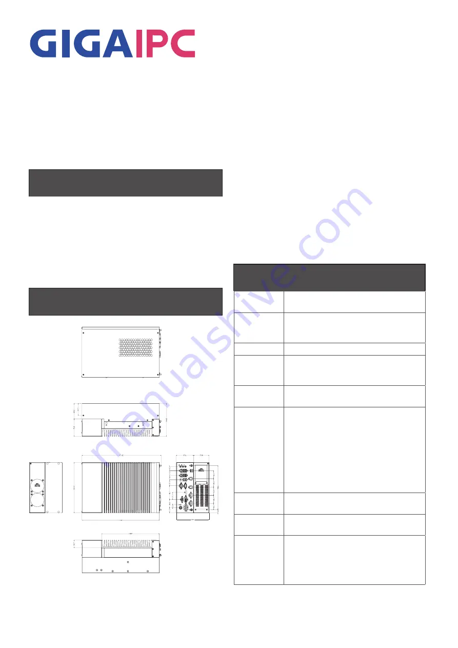
Dimension

Specifications

Dimension

System Size : 224W x 343D x 146H(mm) - 
Discrete GFX max 250W support.(optional)

CPU 

Support for 8/9th Generation Intel® Core™ 
i7/i5/i3 IOTG processors in the LGA1151 
package, TDP under 65W

Chipset

Intel® H310 Express Chipset

Memory

2 x DDR4 SO-DIMM sockets supporting up 
to 32 GB,
Dual channel DDR4 2666/2400 MHz

Ethernet

1 x GbE LAN ports (Intel® i219V)
3 x GbE LAN ports (Intel® i211AT)

Graphic 
Support 

Integrated Graphics Processor - Intel® HD 
Graphics support:
1 x DVI-D port, supporting a maximum 
resolution of 1920 x 1080 @60 Hz
1 x D-Sub port, supporting a maximum 
resolution of 1920 x 1200 @60 Hz
1 x DP port, supporting a maximum 
resolution of 4096 x 2160 @30 Hz
2 independent displays output

Audio

Realtek ALC269 with 2W amplifer
High Definition Audio

Storage 

3 x SATA 6 Gb/s port (Support 2.5" HDD/
SSD)

Expansion 
Slots

1 x M.2 Slot 2230 (E-Key For WiFi + BT)
1 x M.2 Slot 2280 (M-Key support SATA)
1 x Mini-PCIe slot ( USB2.0) with 
SIM Slot
1 x PCIe slot - Discrete riser card support

Caution: DANGER OF EXPLOSION IF 
BATTERY IS INCORRECTLY
REPLACED. REPLACE ONLY WITH THE
SAME OR EQUIVALENT TYPE RECOMMENDED
BY THE MANUFACTURER, DISCARD 
USED BATTERIES
ACCORDING TO THE MANUFACTURER’S
INSTRUCTIONS.

Summary of Contents for QBiX-JMB-CFLA310H-A1

Page 1: ...emory 2 x DDR4 SO DIMM sockets supporting up to 32 GB Dual channel DDR4 2666 2400 MHz Ethernet 1 x GbE LAN ports Intel i219V 3 x GbE LAN ports Intel i211AT Graphic Support Integrated Graphics Processor Intel HD Graphics support 1 x DVI D port supporting a maximum resolution of 1920 x 1080 60 Hz 1 x D Sub port supporting a maximum resolution of 1920 x 1200 60 Hz 1 x DP port supporting a maximum res...

Page 2: ...dity 0 95 non condensing Use wide temperature range memory and storage Vibration During Operation Operation IEC 60068 2 64 3 Grms random 5 500 Hz 1 hr Per Axis With SSD M 2 2280 Non operation IEC 60068 2 6 2 G Sine 10 500 Hz 1 Oct min 1 hr Per Axis Shock During Operation Operation IEC 60068 2 27 50 G half sine 11 ms duration with SSD Packaging Content Box Packing Capacity 1 Carton size 460x315x279...

Page 3: ...VI D Connector 3 DP Digital Display Port 4 COM 1 2 RS 232 422 485 5 COM 3 4 RS 232 6 USB 1 4 x USB 3 0 7 USB 2 2 x USB 2 0 Internal I O Connectors COM3 2 x DDR4 SO DIMM sockets SATA Power Connector 3 x SATA 6 Gb s Connector TMP Connector M2E Slot M2M Slot MINI PCIe Slot Supports SIM SIM Card Slot PCIE X8 Slot PCIE X16 Slot COM4 Front I O Connectors 8 USB C1 2 x USB 2 0 9 LAN 1 Intel i219V 10 LAN 2...

Page 4: ...ode Scription 1 DC_OUT GPU Power Supply Connector DC Output 2 SYS_FAN1 Fan1 Power Connector 3 SYS_FAN2 Fan2 Power Connector 4 PCIEX4 PCIE X4 Slot 5 PCIEX8 PCIE X8 Slot 6 PCIEX16 PCIE X16 Slot DC_OUT SYS_Fan 1 PCIE X4 Slot PCIE X8 Slot PCIE X16 Slot SYS_Fan 2 Expansion Front View Expansion Rear View 3 x I O Bracket System FAN2 System FAN1 ...

Page 5: ...5 www gigaipc com GIGAIPC reserves the right to modify or revise the content at anytime without prior notice System Dimensions ...

Page 6: ...mbain with QBiX JMB CFLA310H A1 and Expansion PCIE Slot Chassis 1 Before disassembling the host please remove the power supply and the cable on the IO Figure 3 Figure 4 2 Use a Phillips screwdriver to remove the screws in the red circle in Figure 5 and Figure 6 3 After the screws are removed open the iron case as shown by the arrow arrow 1 in Figure 9 and then lift it up arrow 2 in Figure 10 to re...

Page 7: ...BiX JMB CFLA310H A1 and Expansion PCIE Slot Chassis 1 Before disassembling the host please remove the power supply and the cable on the IO Figure 3 Figure 4 2 Use a Phillips screwdriver to remove the screws in the red circle in Figure 5 and Figure 6 3 After the screws are removed open the iron case as shown by the arrow arrow 1 in Figure 9 and then lift it up arrow 2 in Figure 10 to remove the cas...

Page 8: ...PCIE Slot Chassis 1 Align the three grooves at the bottom of the case with the three iron posts in the fuselage as shown in Figure 1 and Figure 2 and place them from top to bottom as shown in Figure 3 2 Place the upper edge of the iron shell against the upper edge of the fuselage iron sheet align the screw holes and lock the screws as shown in Figure 5 and Figure 6 to complete the installation 7 8...

Page 9: ...e a screwdriver to remove the screws on the IO baffle plate as shown in Figure 1 and then insert the graphics card into the PCI E slot in Figure 2 from top to bottom 2 Connect the power cord in the extension card to the power connector on the graphics card Figure 3 Figure 6 3 Reinstall the case back to the fuselage and lock the screws 4 3 1 2 5 6 ...

Page 10: ...upports DDR4 SO DIMM type memory module 1 Loosen 4 screws and remove the bottom cover 2 Loosen 4 screws to remove memory thermal cover 3 Affix thermal pad on memory and assemble memory Note Thermal pad and memory thermal cover must be fully mated and compacted 4 Install 4 screws and memory thermal cover 5 Replace the bottom cover and secure with screws ...

Page 11: ...Wifi BT Installation 1 Loosen 4 screws and remove the bottom cover 2 Loosen 4 screws to remove M2E thermal cover 3 Install the module in the M2E Support NGFF 2230 Wifi BT slot and secure with screws 4 Affix thermal pad on M2E card and assemble 5 Install 4 screws and M2E thermal cover 6 Replace the bottom cover and secure with screws ...

Page 12: ...rior notice Storage Installation 1 2 5 HDD SSD 1 Loosen 4 screws and remove the bottom cover 2 Loosen 4 screws to remove storage tray 3 Secure storage with 4 x screws 4 Assemble SATA cable power cable and replace storage tray securely with 4 x screws 5 Replace the bottom cover and secure with screws ...

Page 13: ...2 Loosen 4 screws to remove the hard disk storage aluminum sheet 3 Loosen the 2 screws to remove the aluminum heat sink and thermal pad 4 Assemble the M2M NGFF 2280 SATA storage hard drive 5 Install the 2 screws to securely replace the aluminum heat sink and heat sink paste 6 Install 4 screws to firmly install the hard disk storage aluminum sheet 7 Replace the bottom cover and secure with screws ...

Page 14: ...JMB CFLA310H A1 supports one full size Mini PCIe 1 Loosen 4 screws and then remove the bottom cover 2 Loosen 4 screws to remove the hard disk storage aluminum sheet 3 Assemble the Mini PCIe expansion Card Mini PCIeX1 USB2 0 or 3G 4G SIM Card in SIM Slot 4 Install 4 screws to firmly install the hard disk storage aluminum sheet 5 Replace the bottom cover and secure with screws ...

Page 15: ...avoid damage by transient overvoltage 12 Never pour any liquid into an opening This may cause fire or electrical shock 13 Never open the equipment For safety reasons the equipment should be opened only by qualified service personnel 14 If one of the following situations arises get the equipment checked by service personnel The power cord or plug is damaged Liquid has penetrated into the equipment ...

Reviews: