GEZE ECturn, Wiring Diagram
The GEZE ECturn is a state-of-the-art automatic swing door system designed for effortless accessibility. In order to transform your space, you can effortlessly install the ECturn using the comprehensive wiring diagram provided in the free user manual available for download at manualshive.com. Experience convenience like never before with this innovative product.
Share
Download


Reviews:
No comments
Related manuals for ECturn

TCU Series
Brand: Fandis Pages: 8

SC81
Brand: Falcon Pages: 5

03004
Brand: NA-DE Pages: 2

TIG171 TFT
Brand: R-Tech Pages: 57

MW165
Brand: MAC TOOLS Pages: 20

MIG 155/6W
Brand: Gude Pages: 122

Mig C280 PRO
Brand: ORIGO Pages: 30

ZVZX1010-P
Brand: BENIFERRO Pages: 4

VCD-BS001-VSI
Brand: D+H Pages: 2

JEFPLAS40A-DV
Brand: Jefferson Pages: 20

AIR N ARC I 300 SERIES
Brand: Vanair Pages: 130

Wire Feed 255
Brand: Century Pages: 44

Wire Feed 100
Brand: Century Pages: 56

Hybrid Spot
Brand: Pro Spot Pages: 36
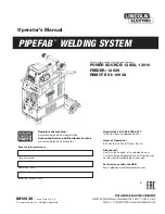
PIPEFAB CE
Brand: Lincoln Electric Pages: 100

NA-5
Brand: Lincoln Electric Pages: 152

PATRIOT PBE180
Brand: Systematics Pages: 28

Power 392A
Brand: Inder Pages: 2


