


1
Geartronics G-Dash 1 user manual
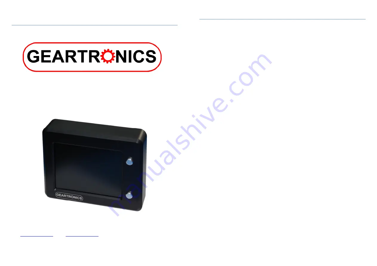
G-Dash Colour Dashboard
Installation & Setup
V1.0.39
(February 2021)
Geartronics Ltd. 50-52 Greenhill Main Road, Sheffield, S8 7RD, ENGLAND. Company registration number: 05729232
Web:
www.geartronics.co.uk
| Email:
2
Table of Contents
•
1 – Hardware specification
Page 3
•
2 – Software Features
Page 4
•
3 – Hardware Installation
Page 5
o
3.1 – Mounting
Page 5
o
3.2 – Wiring & connector pinout
Page 6
•
4 – Software & driver Installation
Page 7
o
4.1 – G-Dash Software installation
Page 7
o
4.2 – Windows Device Driver installation
Page 7
o
4.3 – Initial software connection
page 8
•
5 – Software setup
Page 9
o
5.1 – Basic layout
page 9
o
5.2 – Main window tabs
page 9
o
5.3 – Saving & loading configurations
Page 10
o
5.4 – Start-up splash screen
Page 10
•
6 – Adding display pages
Page 11
o
6.1 – Adding channels to pages
Page 11
•
7 – Adding & configuring data channels
Page 12
o
7.1 – Adding & renaming channels
Page 12
o
7.2 – Configuring channels
Page 12
o
7.3 – Manual CAN setup
Page 12
o
7.4 – Display properties
Page 13
o
7.5 – Display colours
Page 13
o
7.6 – Display limits
Page 14
o
7.7 – CAN data scaling
Page 14
o
7.8 – Configuring analogue input channels
Page 14
o
7.9 – Analogue scaling
Page 14
•
8 – Working with .dbc files
Page 16
•
9 – Working with road car OBDII
Page 17
•
10 – General settings tab
Page 18
o
10.1 – CAN speed
Page 18
o
10.2 – Display orientation
Page 18
o
10.3 – On-board tacho
Page 19
o
10.4 – Vehicle speed measurement
Page 19
o
10.5 – Gear indicator configuration
Page 19
o
10.6 – Calculated gear number
Page 20
•
11 – Alarms
Page 22
o
11.1 – Alarm behaviour
Page 22
o
11.2 – Adding & configuring alarms
Page 22
•
12 – Auxiliary outputs
Page 24
o
12.1 – Configuring auxiliary outputs
Page 24
•
13 – CAN transmit
Page 25
o
13.1 – Configuring a CAN transmit channel
Page 25
•
14 – Engine log
Page 27
•
15 – Data logging
Page 28
o
15.1 – Setting up logging
Page 28
o
15.2 – Uploading & saving logs
Page 29
o
15.3 – Dashview data analysis
Page 29
o
15.4 – Dashview keyboard functions & shortcuts
Page 30
•
16 – Appendix
Page 31
o
16.1 – Brightness adjustment
Page 31
o
16.2 – Display icons
Page 31
o
16.3 – CAN termination
Page 31
o
16.4 – Auxiliary output pull-ups
Page 32
o
16.5 – Odometer and trip function
Page 32


