GEA Grasso RC219, Instruction Manual
The GEA Grasso RC219 comes with a comprehensive Instruction Manual that provides step-by-step guidance for optimal use. This valuable manual is available for free download from our website, ensuring easy access and convenience for users worldwide. Maximize your product's potential by obtaining the manual at manualshive.com.
Share
Download


Reviews:
No comments
Related manuals for Grasso RC219

HG22e/160-4
Brand: GEA Pages: 32

USKT 60 A2
Brand: ULTIMATE SPEED Pages: 122

200-2140
Brand: Powermate Pages: 24

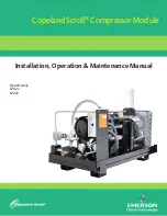
Copeland Scroll ZH56 K4E ZH11 ME Series
Brand: Emerson Pages: 16

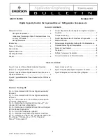
Copeland CORESENSE
Brand: Emerson Pages: 18

CopeLand CoreSense 571-0064-05
Brand: Emerson Pages: 19

Copeland Screw SCA2
Brand: Emerson Pages: 22
COPELAND 3DSDR17ME-TFD
Brand: Emerson Pages: 11

Copeland Scroll ZBKC
Brand: Emerson Pages: 15
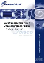
Copeland Scroll ZH 15 K4E
Brand: Emerson Pages: 14

Copeland Scroll ZBH30K Series
Brand: Emerson Pages: 27

Copeland Scroll Digital ZBD114 Series
Brand: Emerson Pages: 31

Copeland Scroll ZB114K5E
Brand: Emerson Pages: 28

Copeland Scroll ZH19K1P
Brand: Emerson Pages: 36

Copeland Scroll K5 Series
Brand: Emerson Pages: 35

Copeland Scroll YBVH021 1U-3E9
Brand: Emerson Pages: 41
Copeland Scroll SZO22
Brand: Emerson Pages: 34

Copeland Scroll YHV 2P Series
Brand: Emerson Pages: 41


