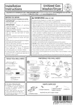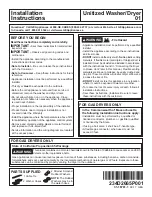


PARTS SUPPLIED
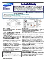
Questions? Call GE Appliances at 800.GE.CARES (800.432.2737) or visit our Web site at: GEAppliances.com
In Canada, call 1.800.561.3344 or visit www.GEAppliances.ca
- Fire Hazard
WARNING
• Appliance installation must be performed by a qualified
installer.
• Install the appliance according to these instructions
and local codes.
•
DO NOT
install a clothes dryer with flexible plastic venting
materials. If flexible metal (semi-rigid or foil-type) duct is
installed, it must be UL-listed and installed in accordance
with the instructions found in “Connecting the Dryer
to House Vent” later in this manual. Flexible venting
materials are known to collapse, be easily crushed and
trap lint. These conditions will obstruct dryer airflow and
increase the risk of fire.
•
DO NOT
install or store this appliance in any location
where it could be exposed to water or weather.
• To reduce the risk of severe injury or death, follow all
installation instructions.
• Save these instructions. (Installers: Be sure to leave
these instructions with the customer.)
In the Commonwealth of Massachusetts,
the following installation instructions apply:
• Installation must be performed by a qualified or
licensed contractor, plumber, or gasfitter qualified
or licensed by the State.
• If using a ball valve, it shall be a T-handle type.
• A flexible gas connector, when used, must not
exceed 3 feet.
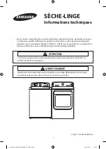
FOR GAS DRYERS ONLY
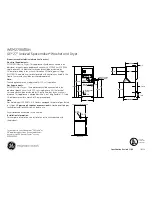
2 Strainer Screens/
Rubber Washers
2 Washer Hoses
1 Cable Tie
234D2665P001
31-16781-1
09-17 GEA
State of California Proposition 65 Warnings
This product contains one or more chemicals known to the State of California to cause cancer, and birth
defects or other reproductive harm.
Gas appliances can cause low-level exposure to some of these substances, including benzene, carbon monoxide,
formaldehyde and soot, caused primarily by the incomplete combustion of natural gas or LP fuels. Exposure to these
substances can be minimized by properly venting the dryer to the outdoors.
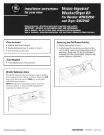
Unitized Washer/Dryer
01
Installation
Instructions
BEFORE YOU BEGIN
Read these instructions completely and carefully.
IMPORTANT
–
Save these instructions for local electrical
inspector’s use.
IMPORTANT
–
Observe all governing codes and
ordinances.
• Install the appliance according to the manufacturer’s
instructions and local codes.
• Note to Installer –
Be sure to leave these instructions
with the Consumer.
• Note to Consumer –
Keep these instructions for future
reference.
• Appliance installation must be performed by a qualified
installer.
• This dryer
must
be exhausted to the outdoors.
• Before the old appliance is removed from service or
discarded, remove the washer and dryer doors.
• Do not allow children on or in the appliance. Close
supervision of children is necessary when the appliance
is used near children.
• Proper installation is the responsibility of the installer.
• Product failure due to improper installation is not
covered under the Warranty.
• Install the appliance where the temperature is above 50°F
for satisfactory operation of the appliance control system.
• Remove and discard existing plastic or metal foil duct
and replace with UL-listed duct.
• Service information and the wiring diagram are located
at the access panel.
NOTE:
The Rubber
Washers may be in
the water hoses
FOR GAS DRYERS ONLY
WARNING
Summary of Contents for GUD27GSSMWWGE
Page 18: ...18 Notes...
Page 19: ...19 Notes...
Page 20: ...20 Printed in Mexico...
Page 38: ...Notes 18...
Page 39: ...19 Notes...
Page 40: ...20 Imprim au Mexique...
Page 58: ...Notas 18...
Page 59: ...19 Notas...
Page 60: ...20...