

4. Insert the battery pack.
5. Close the battery compartment by pushing the door up until it
snaps into place.
6. Place the handset in the charging cradle.
Connecting the Telephone Line
Choose the best location to install your telephone. Your telephone
should be placed on a level surface, such as a desk or table top.
1. Plug one end of the straight telephone line cord into the PHONE
LINE jack on the base.
2. Plug the other end into a wall jack.
3. Set the RINGER switch on the handset to
ON
and place the handset
in the cradle on the base.
NOTE: The charge indicator (on the base) turns on when
the handset is on the cradle, to signal the battery is
charging.
Connecting the Electrical Power
1. Plug one end of the power adaptor cord into the back of the base.
2. Plug the other end into an electrical outlet.
CAUTION: To reduce risk of personal injury, fire, or
damage use only the 5-2608 and/or 5-2769 power
adaptor(s) listed in the user’s guide. This power
adaptor is intended to be correctly orientated in a
vertical or floor mount position.
Battery Backup
This telephone is equipped with a memory holding system powered by
a customer-installed 9-volt alkaline battery (not included).
When electrical power is interrupted, or the electrical line is
unplugged, the battery operates the clock to retain the time of day
and alarm settings in memory. When the unit is running on battery
power, the digital display does not light up; however, if wake time
occurs during the power interruption, the alarm buzzer sounds
(regardless of the type of alarm tone selected) if remaining battery
power is adequate. Normal operation resumes after electrical power
is restored.
To install the backup battery:
1. Open the battery compartment cover located on the bottom of the
base.
2. Connect a fresh 9-volt alkaline battery (not
included). Interlock the large and small
contacts on the battery clip and the battery.
Once connected, place the battery inside the
battery compartment.
3. Replace the battery compartment cover.
Installing the Phone
Installing the Handset Battery
NOTE: You must connect the handset battery before use.
CAUTION: To reduce the risk of fire or personal
injury, use only the Thomson Inc. approved
Nickel-metal Hydride battery model 5-2705 that is
compatible with this unit.
1. Locate battery and battery door which are packaged together
inside a plastic bag and are separate from the handset.
2. Locate the battery compartment on the back of the handset.
3. Plug the battery pack cord into the jack inside the compartment.
NOTE: It is important to maintain the polarity (black
and red wires) to the jack inside the compartment. To
ensure proper battery installation, the connector is
keyed and can be inserted only one way.
NOTE: Alkaline (NEDA 1604A) batteries are
recommended. Carbon-zinc (NEDA 1604) batteries may
be used but memory holding time will be substantially
reduced. Memory holding time for a fresh alkaline
battery is approximately 3 months (if Wake System
is not activated), which should take care of short,
nuisance-type AC power failures. To preserve battery
life, the phone should remain plugged into an AC
electrical outlet. As the battery gets older, its voltage
drops and memory may be lost. Be sure to replace the
battery periodically. A backup battery is not included
with this telephone.
NOTE: If battery is not installed:
a) All alarm time setting memory will be lost if the unit is
unplugged for more than 60 seconds.
b) The clock will stop running during a power outage
period but will start running when power resumes. The
clock will blink to indicate that the time may not be
correct.
IMPORTANT: If storing this unit for more than 30 days,
remove the battery.
Base Setup
Real Time
NOTE: The telephone company sends the current time
and date with the Caller ID (CID) information. If you don’t
manually set the clock time, the unit automatically sets
the time and date when the first call is received.
NOTE: Press the set button at any time to skip to the
next set up step or press the off button to exit to the
main menu.
1. Press and release the set button until
SET REAL TIME
shows in the
display.
2. Press and release the tune + or - buttons to set the time in 1 minute
increments or press and hold to scroll quickly.
3. Press the set button to save. The unit moves to the month setting.
4. Press and release the tune + or - buttons to set the month in 1
month increments or press and hold to scroll quickly.
5. Press the set button to save. The unit moves to the day setting.
6. Press and release the tune + or - buttons to set the day in 1 day
increments or press and hold to scroll quickly.
7. Press the set button to save.
CLK: AUTO
4
MANU
shows in the
display.
8. Use the tune + or - buttons to select
4
AUTO
.
9. Press the set button to save.
KEYTONE:
4
ON
OFF
shows in the
display.
10. Use the tune + or - buttons to select
4
ON
or
4
OFF
.
11. Press the set button to save and the unit returns to the main menu.
Clock Auto Update
If you have manually set the clock, the automatic clock update feature
is disabled. To reset the unit so that the clock will be updated at the
next incoming call;
1. Press the set button
four times
.
CLK: AUTO
4
MANU
shows in the
display.
2. Use the tune + or - buttons to select
4
AUTO
.
3. Press the set button to save and the unit advances to the Keytone
setting menu.
Keytone Setting
If you wish to change the keytone setting;
1. Press the off button for 2 seconds.
2. Use the tune + or - buttons to select
4
ON
or
4
OFF
.
3. Press the set button to save and the unit returns to the main menu.
Display Backlight
Use the display button to adjust the display brightness to desired
setting; low, medium, or high.
NOTE: The unit must be connected to an electrical outlet
to adjust display brightness.
Radio Operation
1. Press and release the audio on/off button to turn the radio on.
2. Press the am/fm button to the select the desired
broadcast band.
3. Press the tune + or - button to select a radio station / frequency.
4. Press the volume control to adjust the listening level (1 through 27).
5. To turn the radio off, press and release audio on/off.
Programming Preset Channels
1. Repeat steps 2 and 3 above.
2. Press and hold a preset channel button (1, 2, 3, 4, or 5) until you hear
a beep. The station’s frequency shows in the display and is stored on
that channel. The default channel is FM 100.9MHZ / AM 520.
3. If desired, repeat step 1 and 2 until all preset channels are
programmed.
Built-in AFC
The built-in Automatic Frequency Control (AFC) works only on FM
mode. It helps keep the radio locked onto the FM stations/frequencies.
FM stereo is a built-in function.
AM Antenna
If you want to listen to an AM frequency radio channel, you need to
connect the AM loop antenna to the jack on the back of the base.
FM Antenna
The power cord acts as your FM antenna. The power cord picks up
moderate to strong signals and eliminates the need for an external
antenna in most strong signal areas. Be sure the power cord is
stretched to its longest length. Do not coil or bunch the cord together.
Changing position of the power cord may improve reception.
Headphone Output
If the headphone jack is inserted into the headphone output jack on
the base unit, the speaker output will be automatically switched to the
headphone terminal.
Auxiliary Audio-In Jack
When the audio on/off button is turned on and an auxiliary audio-in
jack is inserted from an external audio source, the unit automatically
switches from broadcast to the external source and
AUXILIARY AUDIO
shows on the display.
When the auxiliary audio-in jack is removed from the unit, the unit will
automatically switch off and return to stand-by mode.
NOTE: To switch between the external audio source and
radio mode, press and hold the audio on/off key for 2
seconds.
Thomson Inc.
101 West 103rd Street
Indianapolis, IN 46290-1102
© 2007 Thomson Inc.
Trademark(s) ® Registered
Marca(s) ® Registrada(s)
Model 27980
00006068 (Rev. 1 DOM E)
07-21
Printed in China
Equipment Approval Information
Your telephone equipment is approved for connection to the Public Switched
Telephone Network and is in compliance with parts 15 and 68, FCC Rules and
Regulations and the Technical Requirements for Telephone Terminal Equipment
published by ACTA.
1 Notification to the Local Telephone Company
On the bottom of this equipment is a label indicating, among other information,
the US number and Ringer Equivalence Number (REN) for the equipment. You
must, upon request, provide this information to your telephone company.
The REN is useful in determining the number of devices you may connect to
your telephone line and still have all of these devices ring when your telephone
number is called. In most (but not all) areas, the sum of the RENs of all devices
connected to one line should not exceed 5. To be certain of the number of
devices you may connect to your line as determined by the REN, you should
contact your local telephone company.
A plug and jack used to connect this equipment to the premises wiring and
telephone network must comply with the applicable FCC Part 68 rules and
requirements adopted by the ACTA. A compliant telephone cord and modular
plug is provided with this product. It is designed to be connected to a compatible
modular jack that is also compliant. See installation instructions for details.
Notes
•This equipment may not be used on coin service provided by the telephone
company.
• Party lines are subject to state tariffs, and therefore, you may not be able
to use your own telephone equipment if you are on a party line. Check
with your local telephone company.
• Notice must be given to the telephone company upon permanent
disconnection of your telephone from your line.
• If your home has specially wired alarm equipment connected to the
telephone line, ensure the installation of this product does not disable your
alarm equipment. If you have questions about what will disable alarm
equipment, consult your telephone company or a qualified installer.
US Number is located on the cabinet bottom
REN number is located on the cabinet bottom
2 Rights of the Telephone Company
Should your equipment cause trouble on your line which may harm the telephone
network, the telephone company shall, where practicable, notify you that
temporary discontinuance of service may be required. Where prior notice is not
practicable and the circumstances warrant such action, the telephone company
may temporarily discontinue service immediately. In case of such temporary
discontinuance, the telephone company must: (1) promptly notify you of such
temporary discontinuance; (2) afford you the opportunity to correct the situation;
and (3) inform you of your right to bring a complaint to the Commission pursuant
to procedures set forth in Subpart E of Part 68, FCC Rules and Regulations.
The telephone company may make changes in its communications facilities,
equipment, operations or procedures where such action is required in the
operation of its business and not inconsistent with FCC Rules and Regulations. If
these changes are expected to affect the use or performance of your telephone
equipment, the telephone company must give you adequate notice, in writing, to
allow you to maintain uninterrupted service.
Interference Information
This device complies with Part 15 of the FCC Rules. Operation is subject to the
following two conditions: (1) This device may not cause harmful interference; and
(2) This device must accept any interference received, including interference that
may cause undesired operation.
This equipment has been tested and found to comply with the limits for a Class
B digital device, pursuant to Part 15 of the FCC Rules. These limits are designed
to provide reasonable protection against harmful interference in a residential
installation.
This equipment generates, uses, and can radiate radio frequency energy and, if
not installed and used in accordance with the instructions, may cause harmful
interference to radio communications. However, there is no guarantee that
interference will not occur in a particular installation.
Privacy of Communications may not be ensured when using this product.
If this equipment does cause harmful interference to radio or television reception,
which can be determined by turning the equipment off and on, the user is
encouraged to try to correct the interference by one or more of the following
measures:
• Reorient or relocate the receiving antenna (that is, the antenna for radio or
television that is “receiving” the interference).
• Reorient or relocate and increase the separation between the
telecommunications equipment and receiving antenna.
• Connect the telecommunications equipment into an outlet on a circuit
different from that to which the receiving antenna is connected.
SEE MARKING ON BOTTOM / BACK OF PRODUCT
RISK OF ELECTRIC SHOCK
DO NOT OPEN
WARNING:
TO
PREVENT FIRE OR
ELECTRICAL SHOCK
HAZARD, DO NOT
EXPOSE THIS
PRODUCT TO RAIN
OR MOISTURE.
THE LIGHTNING
FLASH AND ARROW
HEAD WITHIN THE
TRIANGLE IS A
WARNING SIGN
ALERTING YOU OF
“DANGEROUS
VOLTAGE” INSIDE
THE PRODUCT.
CAUTION: TO REDUCE THE
RISK OF ELECTRIC SHOCK, DO
NOT REMOVE COVER (OR
BACK). NO USER
SERVICEABLE PARTS INSIDE.
REFER SERVICING TO
QUALIFIED SERVICE
PERSONNEL.
THE EXCLAMATION
POINT WITHIN THE
TRIANGLE IS A
WARNING SIGN
ALERTING YOU OF
IMPORTANT
INSTRUCTIONS
ACCOMPANYING
THE PRODUCT.
CAUTION:
-
-
+
+
Battery clip
Battery
Handset
Base
AC power
adaptor
Telephone line
cord
Handset
battery
If these measures do not eliminate the interference, please consult your dealer
or an experienced radio/television technician for additional suggestions. Also, the
Federal Communications Commission has prepared a helpful booklet, “How To
Identify and Resolve Radio/TV Interference Problems.” This booklet is available
from the U.S. Government Printing Office, Washington, D.C. 20402. Please specify
stock number 004-000-00345-4 when ordering copies.
Notice: The changes or modifications not expressly approved by the party
responsible for compliance could void the user's authority to operate the
equipment.
Hearing Aid Compatibility (HAC)
This telephone system meets FCC standards for Hearing Aid Compatibility.
Licensing
Licensed under US Patent 6,427,009.
FCC RF Radiation Exposure
Statement
This equipment complies with FCC RF radiation exposure limits set forth for an
uncontrolled environment. This equipment should be installed and operated
with a minimum distance of 20 centimeters between the radiator and your
body. This transmitter must not be co-located or operated in conjunction with
any other antenna or transmitter.
Telephone Jack Requirements
To use this phone, you need an RJ11C type
modular telephone jack, which might look like
the one pictured here, installed in your home. If
you don’t have a modular jack, call your local
phone company to find out how to get one
installed.
Installation
Digital Security System
Your cordless phone uses a digital security system to protect against
false ringing, unauthorized access, and charges to your phone line.
When you place the handset in the base, the unit verifies its security
code. After a power outage or battery replacement, you should place
the handset in the base for about 20 seconds to reset the code.
INSTALLATION NOTE: Some cordless telephones
operate at frequencies that may cause or receive
interference with nearby TVs, microwave ovens, and
VCRs. To minimize or prevent such interference, the
base of the cordless telephone should not be placed
near or on top of a TV, microwave oven, or VCR. If such
interference continues, move the cordless telephone
farther away from these appliances. Certain other
communications devices may also use the 2.4 GHz
frequency for communication, and, if not properly set,
these devices may interfere with each other and/or your
new telephone. If you are concerned with interference,
please refer to the owner’s manual for these devices
on how to properly set channels to avoid interference.
Typical devices that may use the 2.4 GHz frequency for
communication include wireless audio/video senders,
wireless computer networks, multi-handset cordless
telephone systems, and some long-range cordless
telephone systems.
Important Installation Guidelines
• Avoid sources of noise and heat, such as motors, fluorescent
lighting, microwave ovens, heating appliances and direct
sunlight.
• Avoid areas of excessive dust, moisture and low temperature.
• Avoid other cordless telephones or personal computers.
• Never install telephone wiring during a lightning storm.
• Never install telephone jacks in wet locations unless the jack is
specifically designed for wet locations.
• Never touch non-insulated telephone wires or terminals, unless
the telephone line has been disconnected at the network
interface.
• Use caution when installing or modifying telephone lines.
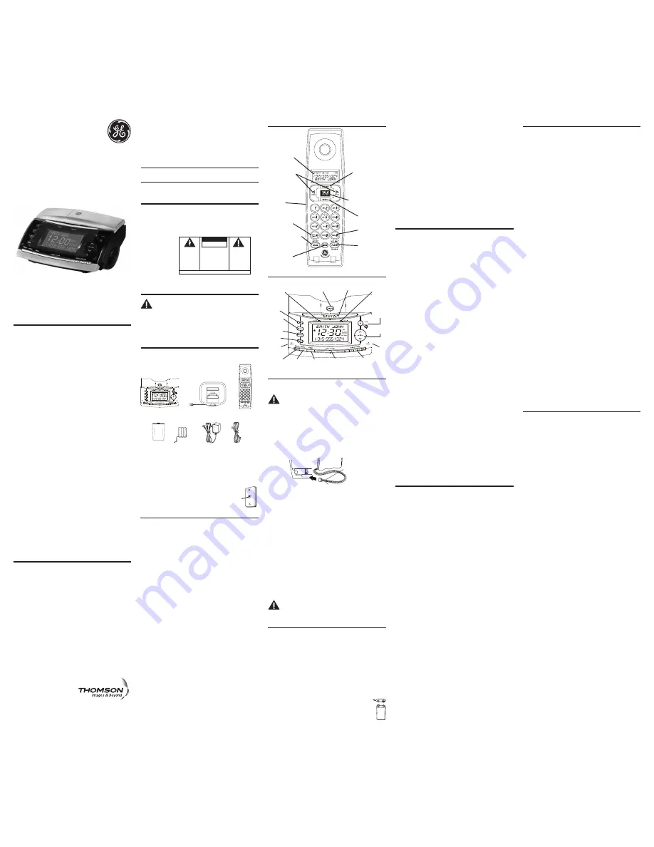
sleep
(button)
alarm 2
(button)
alarm 1
(button)
am/fm
(button)
set
(button)
page
(button)
audio
on/off
(button)
snooze
(button)
volume
control
radio
channel
tuning
Introduction
CAUTION: When using telephone equipment, there
are basic safety instructions that should always
be followed. Refer to the IMPORTANT SAFETY
INSTRUCTIONS provided with this product and save
them for future reference.
IMPORTANT: Because cordless phones operate on
electricity, you should have at least one phone in your
home that isn’t cordless, in case the power in your
home goes out
Before You Begin
Parts Checklist
Make sure your package includes the following items:
display
(button)
headphone
jack
charge
(indicator)
new call
(indicator)
radio presets
(buttons)
auxiliary
audio in
jack
AM Loop
antenna
Model 27980
2.4 GHz Cordless
BedroomPhone™
User’s Guide
Modular
telephone
line jack
Wall plate
Handset Layout
FLASH/
CALL WAIT/
PROGRAM
(button)
CHAN/DELETE
(channel/delete
button)
MEM
(memory button)
EXIT/TONE*
(button)
TALK/CALL BACK
(button)
FORMAT
(button)
display
REDIAL
(button)
Base Layout
off
(button)
ringer
switch
Handset Setup
Programmable Menus
There are five programmable menus available: Language, Local
Area Code, Ringer Tone, Tone/Pulse and Factory Default. When you
program these settings, make sure the phone is
OFF
(not in talk mode).
Pressing the EXIT/TONE* button will remove you from the menu
selection process without changing the feature you are in.
Display Language
1. Press the FLASH/CALL WAIT/PROGRAM button until
1ENG 2FRA
3ESP
shows in the display.
2. Use the CID/VOL (
3
or
4
) button or the handset number pad to
select 1 (English), 2 (French), or 3 (Spanish). The default setting is
1ENG.
3. Press the FLASH/CALL WAIT/PROGRAM button to save and to
advance to the next menu feature.
Local Area Code
If you enter your local 3-digit area code in the area code menu, your
local area code does not display on the Caller ID (CID) list. Instead, you
only see the local 7-digit number. Calls received from outside your
local area code will display the full 10-digit number.
1. Press the FLASH/CALL WAIT/PROGRAM button until
AREA CODE - - -
shows in the display.
2. Use the handset number pad to enter your 3-digit area code. The
default setting is - - -.
NOTE: If you make a mistake, press the CHAN/DELETE button
to erase the incorrect area code and repeat step 2.
3. Press the FLASH/CALL WAIT/PROGRAM button to save and to
advance to the next menu feature.
Ringer Tone
1. Press the FLASH/CALL WAIT/PROGRAM button until
RINGER TONE
shows in the display.
2. Use the CID/VOL (
3
or
4
) button or the handset number pad (1-3)
to enter your selection from Ringer Tone 1, 2, or 3. The default
setting is
RINGER TONE 1.
3. Press the FLASH/CALL WAIT/PROGRAM button to save and to
advance to the next menu feature.
Tone/Pulse
1. Press the FLASH/CALL WAIT/PROGRAM button until
1 TONE 2 PULSE
shows in the display.
2. Use the CID/VOL (
3
or
4
) button or the handset number pad to
enter your selection. The default setting is
1 TONE.
3. Press the FLASH/CALL WAIT/PROGRAM button to save and to
advance to the next menu feature.
Factory Default
This feature allows you to restore the handset’s original features.
1. Press the FLASH/CALL WAIT/PROGRAM button until
DEFAULT
shows
in the display.
2. Use the CID/VOL (
3
or
4
) button to switch between
YES or NO
. The
default setting is
NO.
3. Press FLASH/CALL WAIT/PROGRAM to save. You will hear a
confirmation tone.
Alarm Setup
NOTE: Press the off button at any time to exit setup
menu and leave settings unchanged.
Set Alarm Type
This Bedroom Phone is equipped with two alarms. The alarms can be
set independently to either radio or buzzer.
1. Press and hold alarm 1 or alarm 2 button for two seconds. A tone
will sound and the current alarm status is displayed.
2. Press the button again to select the desired type of alarm (radio,
buzzer or alarm off). The corresponding icon shows in the display. A
music note indicates that the alarm is set to radio, a bell indicates
that the alarm is set to buzzer.
3. Press the set button to save and confirm setting.
SET ALARM TIME
shows in display. Refer to step 3 of the Set Alarm Time section for
further instructions.
- OR -
If no action is taken, unit will exit menu and return to stand-by mode.
Set Alarm Time
1. Press and hold the alarm 1 or alarm 2 button for two seconds.
2. Press the set button.
3. Use the tune + or - button to set the wake time. Press and hold to
quickly increase or decrease the increments.
4. Press the set button to save and confirm setting.
ALARM LENGTH
shows in display. Refer to step 3 of the Set Alarm Time section for
further instructions.
- OR -
If no action is taken, unit will exit menu and return to stand-by mode.
Set Alarm Length
1. Press and hold the alarm 1 or alarm 2 button for two seconds.
2. Press the set button
twice
.
3. Press the tune + or - button to set the length time. Alarm length can
be set from 15 minutes to 2 hours.
4. Press the set button to save and confirm setting. The display shows
ALARM 1
(or
2
)
, or if in Radio Alarm mode the most recently tuned
channel. Refer to step 3 of the Set Radio Alarm Preset Channel
section for further instructions.
- OR -
If no action is taken, unit will exit menu and return to stand-by mode.
Set Radio Alarm Preset Channel
1. Press and hold the alarm 1 or alarm 2 button for two seconds.
2. Press the set button
three times
.
3. Press the tune + or - button to scroll through the preset
(1-5) channels to select a channel for the alarm. The frequency
shows on the display. If no radio preset button is pressed, the
channel for the alarm will be the most recent tuned channel.
4. Press the set button to save and confirm setting.
ALARM 1
(or
2
)
VOL
= XX
shows on the display,
XX
is the most recent selected volume
level. Refer to step 3 of the Set Alarm Volume section for further
instructions.
- OR -
If no action is taken, unit will exit menu and return to stand-by mode.
Set Alarm Volume
1. Press and hold the alarm 1 or alarm 2 button for two seconds.
2. Press the set button
four times
.
3. Press volume up or down button to select desired volume level (1
through 27).
4. Press the set button to save and confirm setting and unit will return
to idle model.
PAUSE#
(button)
Battery
compartment
cover
CID/VOL
(buttons)
black wire
red wire
battery
pack
PRESS DOWN
FIRMLY


