background image

www

.

technolo

gysupplie

s

.

co.uk

content visit -

drivers and do

wnloadable

For hints

, tips, FAQ

’s,

4

e

u

s

s

I

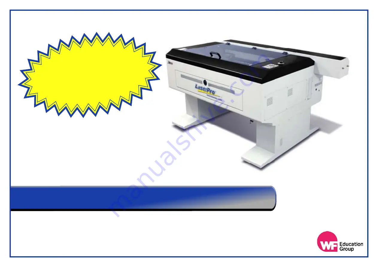
 User Guide - X252 & X380

e strongly recommend that you read and/or print out that manual.

W

machine. 

This can be found on the GCC CD ROM, supplied with your 

s user manual. 

’r

conjunction with the manufacture

 a manual. It should therefore be read in 

This document is designed as a quick step training guide and NOT

2021

Summary of Contents for LaserPro X252

Page 1: ...Guide X252 X380 e strongly recommend that you read and or print out that manual W machine This can be found on the GCC CD ROM supplied with your s user manual r conjunction with the manufacture a man...

Page 2: ...account Please notify us of any shortages or damage within 3 days of delivery and in the case of non delivery with 10 days of the date of invoice Any goods conveyed to customers remain the property o...

Page 3: ...Photograph Using 2D Design 30 CorelDraw Setup For Lasers 36 Example Project Using CorelDraw 39 How To Engrave A Photograph Using CorelDraw 42 Setting Up The Laser Machine 44 Setting Up The Printer Dri...

Page 4: ...to arrange a technician s visit Becasue of the nature of the product if your laser needs repair after the warranty period the repair must only be carried out by an authorised service technician Furth...

Page 5: ...fully before operation E F T P d n a n o l f e T C V P s a h c u s s e c n a t s b u s c i x o t e c u d o r p y a m t a h t s l a i r e t a m r e h t o r o s e c a f r u s e v i t i s n e s t a e h s...

Page 6: ...Balsa Greyboard Cardboard Ceramics Kevlar Vinyl GEFF Plastazote Plastazote Below is a list of known materials which are to be used in the laser cutter as they will produce corrosive fumes that will b...

Page 7: ...ock if fitted to all models to prevent access to the working area during laser operation whilst the laser is firing The interlock system will also not allow the laser to be fired without the extractio...

Page 8: ...id particles may need changing every couple of months The main filter which is a combined activated carbon and HEPA filter which is for fine particles and odour may last six months to a year all depen...

Page 9: ...ith cream cleaners such as Cif on a damp cloth and then dried Ensure that the machine is disconnected from the mains power These are the most important parts of the laser for ensuring efficient cuttin...

Page 10: ...N B PLEASE MAKE SURE THE LASER MACHINE IS DISCONNECTED FROM THE MAINS POWER BEFORE OPENING THE TUBE ACCESS PANEL Step 2 Simply remove the screws as shown below this will then allow you to slide the b...

Page 11: ...B Mirror A is the Red Beam mirror and only has to be cleaned if you can no longer see the red beam on the laser bed material as this mirror only bounces the red light beam NOT the laser cutting beam...

Page 12: ...cover To do this you need to remove the bottom two screws and loosen off the top screw This enables you to swing the cover over and gives access to slide the items out Ensure that the mirror and lens...

Page 13: ...fter cleaning they insert the mirror and the lens into the wrong locations Please see pictures below explaining how to locate these parts correctly Mirror 3 4 location This mirror will locate above th...

Page 14: ...dirty you may have to repeat this process several times with a new paper each time The fluid will evaporate leaving a clean and shiny surface After a period of time a film of cleaning fluid will build...

Page 15: ...e dust particles DO NOT apply grease or oil to the motion system tracks The grid bed cutting table will over time take on a black stained appearance around the area most used for cutting In most cases...

Page 16: ...ed level Temperature Indicator Warning Light Safe running light Outlet pipe connection On Off power switch H Ho ow w Of ft te en n Do o Yo ou u Ch ha an ng ge e Yo ou ur r Wa at te er r Inlet pipe con...

Page 17: ...ce it has finished Press F4 Function on the laser main menu control panel Step 2 In the next screen you will see a black diamond to the left hand side of your options Move the diamond using the up and...

Page 18: ...bring this screen up is by selecting restart from the power options menu on Windows 8 it s under Charms or on the login screen and in Windows 10 it s on the Start Menu Hold down the SHIFT key while yo...

Page 19: ...the driver select Do Not Share and Do Not Print A Test Page Step 7 Click OK then Select Next Step 8 Then select Next and then click OK To test that the machine is connected correctly you should go ba...

Page 20: ...ep 1 Go to the Windows start button in the bottom left hand corner of Windows Then go to Devices and Printers Windows 7 Step 2 Right click on your laser cutters printer driver and select properties at...

Page 21: ...cutters power and speeds Note Once the recommended setup has been completed it will be applied to any software that you will be using in Windows ie Coral Draw 2D Design etc Step 7 Option Manual Colou...

Page 22: ...esign V2 on your computer and select from the tool bar at the top of the screen Step 2 Customise Operation On the drop down menu that appears simply go down to and then across to the right to this wil...

Page 23: ...m mode 2 to the and Bitmap Modes mode 1 Step 4 Click OK to return you back to the main screen Step 5 Setup Set as Default Once you are back at the main screen go up to on the top tool bar of 2D Design...

Page 24: ...in the laser cutter How to assign the custom colours to define the order in which the design will be cut and or engraved For how to perform the design process itself please use the training demonstrat...

Page 25: ...a later stage in the printer driver setup Then you can click OK Step 5 Your 2D Design page will now represent the size of the material in the laser cutter Y axis X axis Step 3 User Defined Select the...

Page 26: ...til the final part of the project has been completed Step 1 After you have designed or loaded up your project you will need to select the parts of the design you want to assign a particular colour to...

Page 27: ...will see that the first three of the custom colours are in the recommended order Simply click on the colour you want to assign to the part parts selected and then click OK Once you deselect the lines...

Page 28: ...o to and then Select your photo from the saved location Step 1 Import File on your computer Note You can also use the copy and paste option to import a bitmap colour images can be used Once you have i...

Page 29: ...s you normally would but in the Options tab when you select the greyscale engrave mode called Black and White a new tab called Raster will appear in the print properties Contrast This is where you can...

Page 30: ...tor functions correctly The colour palette that you use to setup your project cut order will not match up with the printer driver colours and finally the program will not let you engrave a photograph...

Page 31: ...elect the pen tip icon then select the same icon from the menu that appears If the pen icon is not present please press F12 on the keyboard Step 3 From the pop up window that appears make sure that th...

Page 32: ...t the software will communicate the correct line thickness to the laser cutter This setting needs to be changed on every computer that a student is using to design if it isn t then files that have bee...

Page 33: ...s on the top toolbar and then Color Management then across to Default Settings Step 7 From the window that opens up select the Presets drop down menu and from the list select the option Simulate Color...

Page 34: ...cut out at the same time you will firstly need to draw something on the design page This will enable you to select the Print option from the File menu on the top toolbar Step 9 Select your laser cutte...

Page 35: ...reformed by drop down menu select your laser cutter then click Apply then select Cancel Step 11 Finally go to Tools on the top toolbar and select Save Settings As Default CorelDRAW will now be setup t...

Page 36: ...he laser cutter How to assign the colours to define the order in which the design will be cut and or engraved This guide will run through how to set your page size in CorelDRAW so that it matches the...

Page 37: ...he job red is the second and green is your third part of the job It s by inputting the power and speed settings that determine whether the colour will be cut or engraved along with setting either a fi...

Page 38: ...you would like to change your selected part to Right clicking the colour will change the colour and left clicking on the colour will change the colour Tip line fill Black Green Red Simply repeat this...

Page 39: ...ve a photograph bitmap image using your CorelDraw software Step 1 With your CorelDraw page open go to File on the top toolbar then select Import from the drop down menu Step 2 Select the image from it...

Page 40: ...mage and go to Bitmaps on the top toolbar From the drop down menu that now appears select the first option Convert to Bitmap Step 4 A pop up window will appear on screen From the drop down menu select...

Page 41: ...inter driver the same as you normally would but when you select the options tab select the greyscale engrave mode called Black and White and a new tab called Raster will appear in the print properties...

Page 42: ...once this will bring up the It is easier and quicker to grab the laser head and move it to your desired location you will not damage the machine doing this If the head will not move carriage moving s...

Page 43: ...r the material Step 5 Auto Focus button on the control panel Shown below this will raise the material to contact the auto focus probe which will in turn lower the material ensuring that the lens insid...

Page 44: ...n 2D Design or CorelDRAW simply select File and then Print Step 2 Select the name of your laser cutter from the Printer name section and then click on the properties button Note When you select proper...

Page 45: ...ages 3D Mode This is for use with Images that have a black background and a white foreground Stamp Mode This allows you to taper the sides of the engrave so that the base of your design will have more...

Page 46: ...settings at the back of this manual To input the settings simply move the slider bars left or right for the required settings Adjust the slider bars here Always leave these two options ticked to set t...

Page 47: ...eveal the image when processing whereas top to bottom can obstruct your view during the engraving process Position Mode This mode will determine the start point of your project in the laser cutter Out...

Page 48: ...he rotary attachment with the laser This will then ask for extra information See rotary section of the manual for details D Step 7 OK OK Once you have completed your file setup then you can click and...

Page 49: ...t initialisation process The rotary attachment is an optional item for the GCC Laser cutters It adds a 4th axis that provides the capability of engraving onto cylindrical objects suchs as glasses vase...

Page 50: ...tachment To do this simply remove the bottom two screws and loosen the top screw then swivel the face plate clockwise as shown in the image below left This will enable access to the cone which slides...

Page 51: ...wn arrows will now rotate the cone on the rotary attachment Note not If the laser does activate the lower trip switch then turn the laser power This OFF will mean that the laser cutter has not recogni...

Page 52: ...nto the laser printer driver at a later stage To get this measurement you will need to move the laser head to the right until the red beam pointer hits the edge of your glass on the cone see Fig 1 You...

Page 53: ...he your Y axis will be the width of the object multiplied by 3 14 Once you have entered these values your page size now represents your object unravelled as a flat piece of material Step 3 Rotate your...

Page 54: ...e diameter Step 3 Insert the offset acquired at step 12 Useful Rotary Attachment Information Printer Driver Setup for Rotary Attachment Information The smallest diameter that can be fitted to the rubb...

Page 55: ...the laser cutter has been triggered before the auto focus probe could focus Step 2 From the main screen on the laser cutter control panel press any directional arrow once to bring up the carriage movi...

Page 56: ...control panel commands from the main menu Deleting a file F4 Enter then press either F3 to delete a single file or F4 to delete all files Press F4 twice Sending the laser head to HOME During operatio...

Page 57: ...h any fire that may break out Therefore NOT do not leave the laser unattended during operation If you have to disable the SMART Guard we would always recommend that you enable it after finishing your...

Page 58: ...By Checked By Checked By Mirror 1 Mirror 2 Mirror 3 Mirror 4 2 Inch Lens Collimating Lens Motion System Tracks Auto Focus Probe Grid Bed Stainless Steel Bed Underneath the bed Extraction Filters Chil...

Page 59: ...is mode simply look for the enhanced vector box to be checked in the Advance tab in the print properties setting See Right Note If your enhanced vector box is ticked then all you need to do when input...

Page 60: ...MDF 9mm MDF 12mm LaserPly4mm LaserPly6mm LaserPly9mm LaserPly12mm HIPS 1mm HIPS 1 5mm HIPS 2mm HIPS 3mm Polypropylene Fabric Greyboard 3 2mm Correx Speed Power PPI Speed Power PPI Speed Power PPI Spee...

Page 61: ...Page 61 Speed Power PPI Material Speed Power PPI Material Speed Power PPI Material Speed Power PPI Material Speed Power PPI Material Speed Power PPI Material Personal Material Settings Sheet...

Page 62: ...ters as the X Y measurement this can also be left at the maximum laser bed size if preferred An error warning will be displayed on the Print window if this size is smaller than the page paper size in...

Reviews:

Related manuals for LaserPro X252