


1
www.gateway.com
Replacing the AC Adapter
Technical Support
See the label on the bottom of the notebook for Customer
Care Information. See your
Reference Guide
for important
safety, regulatory, and legal information.
© 2007 Gateway, Inc. All rights reserved. Gateway and
eMachines are trademarks or registered trademarks of
Gateway, Inc. in the United States and other countries.
All other brands and product names are trademarks or
registered trademarks of their respective companies.
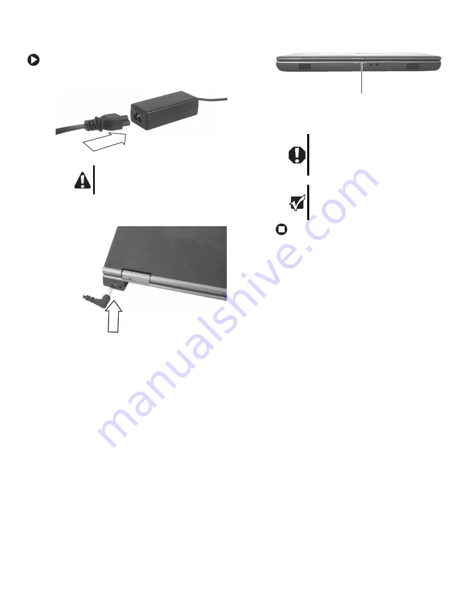
Replacing the AC Adapter
To connect the AC adapter:
1
Connect the power cord to the AC adapter.
2
Connect the AC adapter to your notebook’s power
connector.
3
Plug the power cord into a wall outlet. The power
indicator turns on.
If the power indicator does not turn on, unplug the
adapter from your notebook, then plug it back in.
Caution
Replace the power cord if it becomes damaged.
The replacement cord must be of the same type
and voltage rating as the original cord or your
notebook may be damaged.
Warning
Do not attempt to disassemble the AC adapter.
The AC adapter has no user-replaceable or
user-serviceable parts inside. The AC adapter
has dangerous voltages that can cause serious
injury or death. Contact Gateway about returning
defective AC adapters.
Important
If the battery charge indicator does not turn blue
after three hours, contact Gateway Customer
Care at the Web address or telephone number
shown on the label on the bottom of your
notebook.
Power indicator


