Gatekeeper G4-504HD2a, User'S Operating Manual
The Gatekeeper G4-504HD2a user's operating manual is available for free download on our website. This comprehensive manual provides step-by-step instructions and troubleshooting tips for optimal use of your Gatekeeper G4-504HD2a. Enhance your user experience by accessing the manual at manualshive.com today!
Share
Download


Reviews:
No comments
Related manuals for G4-504HD2a

H20HVR1616I
Brand: Smartwatch Pages: 20

DVR-16TN Series
Brand: Speco Pages: 2

SW-0001A
Brand: SD-MDVR Pages: 36

ARK-2250S
Brand: Advantech Pages: 80

VT-EHL Series
Brand: Vitek Pages: 96
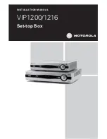
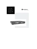
SET-TOP BOX VIP1216
Brand: Motorola Pages: 27

DCT3080
Brand: Motorola Pages: 2

DCT3400 Series
Brand: Motorola Pages: 2

DCT3416
Brand: Motorola Pages: 2

DCX3501-M
Brand: Motorola Pages: 16

QIP27 Series
Brand: Motorola Pages: 33

DCT6400 Phase III
Brand: Motorola Pages: 41

VIP 1910
Brand: Motorola Pages: 16

DCX3400 Series
Brand: Motorola Pages: 2

DCT6400 Series
Brand: Motorola Pages: 62
DCT6400 Series
Brand: Motorola Pages: 43

DCH3416
Brand: Motorola Pages: 48

DCX3400 Series
Brand: Motorola Pages: 55


