Garmin GPSMAP 8 10 Series, Owner'S Manual
Introducing the Garmin GPSMAP 8 10 Series – a cutting-edge navigation solution for explorers. Ensure smooth journeys with this advanced GPS device, backed by an intuitive Owner's Manual. Download the comprehensive manual for free and unleash the true potential of your Garmin GPSMAP 8 10 Series at manualshive.com.
Share
Download


Reviews:
No comments
Related manuals for GPSMAP 8 10 Series

LMU-5000
Brand: CalAmp Pages: 55

4230
Brand: Cal Amp Pages: 10
UNIVERSAL TRACKER
Brand: TRACKIMO Pages: 19

T366
Brand: MeiTrack Pages: 23

CF LP GPS
Brand: Transplant Computing Pages: 30

GM720
Brand: Navibe Pages: 8

CVUK-TR14-VER2
Brand: Chinavision Pages: 26

6 Cabin
Brand: Geonav Pages: 85

ION ELITE 362150
Brand: Bushnell GOLF Pages: 88

HawkEye 6300 Mk1
Brand: Blue Sky Network Pages: 11
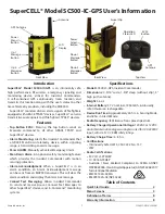
SC500-IC-GPS
Brand: SuperCELL Pages: 8

T802
Brand: AOYA Pages: 2

Ct-AVL688
Brand: Connectec Pages: 13

NAV+
Brand: Coyote Pages: 112

MH 1000
Brand: MobileHelp Pages: 12

50
Brand: II Morrow Inc. Pages: 324

TAGG3W
Brand: TAGG Pages: 16

Sapphire RGM-2000
Brand: RoyalTek Pages: 45


