Garmin GMX 200, Pilot'S Manual & Reference
The Garmin GMX 200 is a versatile avionics unit that enhances navigation and situational awareness. To ensure a smooth installation experience, a comprehensive Installation Manual is available for free download from our website. Get the most out of your GMX 200 by accessing the manual at manualshive.com.
Share
Download


Reviews:
No comments
Related manuals for GMX 200
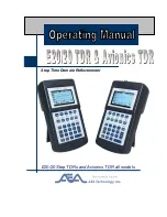
E20/20
Brand: AEA Technology, Inc. Pages: 126
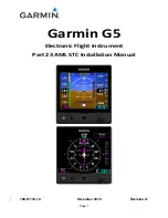
Approach G5 - GPS-Enabled Golf Handheld
Brand: Garmin Pages: 285
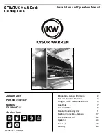
DX6LN-MCU
Brand: Kysor/Warren Pages: 29

VA903MB - 19" LCD Monitor
Brand: ViewSonic Pages: 2

IFD410 FMS/GPS
Brand: Avidyne Pages: 380

ISOLA BAHIA
Brand: Tecfrigo Pages: 60

NDC-014-SG
Brand: New Air Pages: 28


