background image

   Part # 4532285 Rev 4 (4/29/14) 


© 2013 Garland Commercial Ranges Limited 
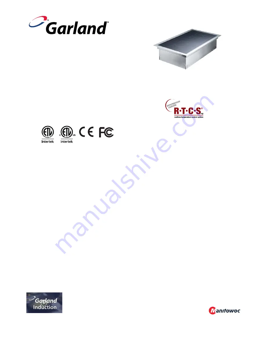


Models: 

SH DU IN 7000   (2x3500 / 7kW) 

   SH DU IN 10000 (2x5000 / 10kW) 


INSTALLATION AND 

OPERATION MANUAL 

GARLAND INDUCTION 

BUILT-IN LINE 

DUAL-ZONE COOKERS 

with RTCSmp TECHNOLOGY 

R

eal-time 

T

emperature 

C

ontrol 

S

ystem 

m

ulti-

p

oint sensing


PLEASE READ ALL SECTIONS OF THIS MANUAL AND 
RETAIN FOR FUTURE REFERENCE.


THIS PRODUCT HAS BEEN CERTIFIED AS 
COMMERCIAL COOKING EQUIPMENT AND MUST BE 
INSTALLED BY PROFESSIONAL PERSONNEL AS 
SPECIFIED 

INSTALLATION

 AND ELECTRICAL CONNECTION 

MUST COMPLY WITH CURRENT CODES IN YOUR 
REGIION: 
IN CANADA – THE CANADIAN ELECTRICAL CODE 
PART 1 AND / OR LOCAL CODES. 
IN USA – THE NATIONAL ELECTRICAL CODE ANSI / 
NFPA – CURRENT EDITION. 

FOR YOUR SAFETY


DO NOT STORE OR USE GASOLINE OR OTHER 
FLAMMABLE VAPORS OR LIQUIDS IN THE VICINITY OF 
THIS OR ANY OTHER APPLIANCE


CE models

 comply with the latest European 

Norms: 
EN 60335-1, EN 60335-2-36, EN 62233 (EMC/EMV) 

North American models

: ETL listed in compliance 

with UL 197, CSA C22.2 No.109, NSF-4 
Complies with FCC part 18, ICES-001


WARNING


IMPROPER INSTALLATION, ADJUSTMENT, 
ALTERATION, SERVICE OR MAINTENANCE CAN 
CAUSE PROPERTY DAMAGE, INJURY, OR DEATH. 
READ THE INSTALLATION, OPERATING AND 
MAINTENANCE INSTRUCTIONS THOROUGHLY 
BEFORE INSTALLING OR SERVICING THIS 
EQUIPMENT


Users are cautioned that maintenance and repairs must be performed by a Garland authorized service agent using only 
genuine Garland replacement parts. Garland will have no obligation with respect to any product that has been improperly 
installed, adjusted, operated or not maintained in accordance with national and local codes and/or installation instructions 
provided with the product or any product that has its serial number defaced, obliterated or removed, and/or which has been 
modified or repaired using unauthorized parts or by unauthorized service agents. For a list of authorized service agents 
and/or genuine replacement parts, please visit our website at 

www.garland-group.com (USA and Canadian customers) or 

www.manitowocfoodservice.com  (international customers).

 The information contained herein, including design and part 

specifications, may be superseded and is subject to change without notice. 


Visit our 

Video Gallery

 at 

www.Garland-Group.com 


Summary of Contents for SH DU IN 10000

Page 1: ...s with FCC part 18 ICES 001 WARNING IMPROPER INSTALLATION ADJUSTMENT ALTERATION SERVICE OR MAINTENANCE CAN CAUSE PROPERTY DAMAGE INJURY OR DEATH READ THE INSTALLATION OPERATING AND MAINTENANCE INSTRUCTIONS THOROUGHLY BEFORE INSTALLING OR SERVICING THIS EQUIPMENT Users are cautioned that maintenance and repairs must be performed by a Garland authorized service agent using only genuine Garland repla...

Page 2: ...NG SYMBOLS This symbol alerts you to a hazardous situation that WILL or COULD cause serious bodily harm or death Be alert and implement relevant safety precautions This dangerous voltage warning symbol indicates a risk of electric shock and hazards from dangerous voltage CAUTION This symbol alerts a hazardous situation which if not avoided COULD cause minor to moderate personal injury or property ...

Page 3: ... 4 3 1 Built In Induction Unit Installation 9 4 3 1 1 Dimensions Dual Zone RTCSmp Built In SHDUIN7000 10000 9 4 3 1 2 Top Mount Flush Mount and Dimensions 9 4 3 1 3 Compartment Protection and Clearance 10 4 3 1 4 Parallel Installation and Clearance 10 4 3 1 5 Installation Steps 11 4 3 2 Control Unit Installation 12 4 3 2 1 Front Mount 12 4 3 2 2 Back Mount 12 4 3 2 3 Dimensions Control Unit RTCSmp...

Page 4: ...ry due to burns from contacting overheated cooking surface cookware or oil and grease Damage to the induction unit caused by using unsuitable cookware 1 2 Safety Instructions for Operator Please follow the following rules to avoid personal injuries and property damages When the unit is in use heat transfers from cookware to the glass top the glass top can become hot To avoid burn injuries do not t...

Page 5: ...be operated within the limits provided in the technical specifications Please also refer to chapter 9 Important Rules for using induction equipment 1 4 Unauthorized Modification and Use of Spare Parts Please contact Garland if you intend to make any changes on the induction unit For safety reasons always use genuine parts and accessories approved by Garland Any unauthorized modification as well as...

Page 6: ...n units Built with a robust construction the induction units are compact and powerful with the revolutionary RTCSmp Technology Realtime Temperature Control System with Multi Point sensing The RTCSmp Technology monitors the energy supply the state of the induction coil power board CPU and the cooking zones in realtime The essential features are Drop in flush mounted design with CrNi Steel body belo...

Page 7: ...5lb 25kg 55 1lb 3 4 Electrical Specifications Voltage Power Conductor Size 7kW Model 208 V AC 3Ph 60Hz 7000 W 2x 3500W 22A AWG 10 400 V AC 3Ph 50Hz 7000 W 2x 3500W 11A 1 5mm2 440 V AC 3Ph 50Hz 7000 W 2x 3500W 10A 1 5mm2 10kW Model 208 V AC 3Ph 60Hz 10000 W 2x 5000W 30A AWG 8 400 V AC 3Ph 50Hz 10000 W 2x 5000W 16A 2 5mm2 440 V AC 3Ph 50Hz 10000 W 2x 5000W 15A 2 5mm2 3 5 Operating Conditions Max Tol...

Page 8: ...ven counter surface Do not place the induction unit on or near a hot surface or any heat producing equipment such as an oven or a deep fryer Protect the induction unit from steam if the unit is placed next to high steam emitting equipment such as pasta cookers steamers and water bath Allow easy access to the control knobs and ensure the LED lights are not obstructed Keep the induction unit away fr...

Page 9: ...4 3 1 Built In Induction Unit Installation 4 3 1 1 Dimensions Dual Zone RTCSmp Built In SH DU IN 7kW 10kW 4 3 1 2 Top Mount Flush Mount and Dimensions There are two methods to install the built in unit top mount A or flush mount B The counter surface cut out dimensions are different for these two methods TOP MOUNT cut out dimensions on the counter surface 345 x 605mm 13 58 x 23 82 FLUSH MOUNT cut ...

Page 10: ... connected from the unit to the bottom or to the side of the cabinet D If there is no direct path to install the air intake duct make an opening on an inner shelf or wall for the duct to pass through E IMPORTANT Minimum clearance below the counter surface for the unit 204mm 8 03 height x 393mm 15 47 width x 653mm 25 71 depth F Hot air exhaust from the induction unit G Air exhaust opening installed...

Page 11: ...on it is very important to use isopropyl alcohol minimum 70 or equivalent to clean the flange and the counter surfaces where the silicone adhesive will be applied To install the built in unit 1 Apply silicone adhesive PACTAN Part 70000015 provided with the Air Intake Kit to A TOP MOUNT The top of the counter surface where the built in frame will sit B FLUSH MOUNT The top of the support step where ...

Page 12: ... panel 1 Drill holes and make the cut out using the dimensions and the actual unit provided 2 Secure the control unit to the panel with fasteners Illustration Measurements in mm and inch 4 3 2 2 Back Mount NOTE For this type of installation the maximum thickness of the panel must not exceed 1 5mm or 16 gauge This restriction ensures a proper grip on the knob and the LED light will not be obstructe...

Page 13: ...ke See 4 1 Location and 4 2 Ventilation A Air Intake Filter B Air Filter Holder C Air Duct Holder D Clamp x2 E Flex Aluminum Air Duct F Silicone Adhesive PACTAN G Caulking Gun An example of an Air Intake Kit connected to a built in induction unit A Cut Out Opening B Silicone Adhesive PACTAN C Air Exhaust Opening close to the top D Duct mounted to the unit E Flex Aluminum Air Duct max length 244cm ...

Page 14: ...r should be in visible view easily accessible and labeled A blocked filter can cause electronic damage to the induction unit Refer to chapter 7 Cleaning 4 To allow hot exhaust air to escape install in the cabinet an air exhaust opening such as a louvered air duct which must be at least 1 5 times or greater than the air intake opening Depending on the air path and the amount of natural air movement...

Page 15: ...h a mains connection must not be connected to a single fault current protective switch To setup the unit for operation 1 Ensure the control knob is at the 0 OFF position ON Position Any position where 0 is not pointing to the LED light The light is on OFF Position 0 is pointing to the LED light The light is off 2 Remove all objects from the glass top and check that the glass top is neither cracked...

Page 16: ...he control knob to a position between 1 and 12 The LED indicator lamp lights up and the water is heated ON Position Any position where 0 is not pointing to the LED light The light is on OFF Position 0 is pointing to the LED light The light is off 3 Take the pan away from the hob Power transmission stops and the indicator lamp starts to blink 4 Place the pan back on the heating area The LED indicat...

Page 17: ...cially when you heat up oil or grease check the cooking process frequently to prevent the oil or grease from overheating and burning BROIL DRY PROTECTION The RTCSmp electronic temperature control monitors overheating at the pan base When an overheated pan overheated oil empty pan is detected energy transfer from the generator to the pan will be stopped immediately You must turn the unit off let it...

Page 18: ...les temperature controls in realtime To obtain the optimal results from the sensors you must always place the pan in the center of the hob which is indicated by the markings on the glass CAUTION Pans and pots must not cover more than one cook zone Otherwise electronic components of the induction unit can be damaged DO NOT A Place one pan over two cook zones B Place multiple pans on a single cook z...

Page 19: ...eating process is engaged and the indicator light stops flashing and remains bright However the indicator light will keep flashing if the unit is not detecting any pan or an unsuitable pan is placed on the glass top When you remove the pan from the heating area power transfer to the pan is stopped immediately NOTE Pan with a bottom diameter smaller than 5 12 cm is not detected by the system 6 5 Wh...

Page 20: ... once a week or as often as required Garland s Air Intake Filter is dishwasher safe Wipe the filter dry before inserting it back into the Filter Holder The filter is pressure fitted into the Air Filter Holder installed onto the cabinet The filter pops out when you press down on its corners as shown If it doesn t move try the opposite corners Glass and Body Cleaning 1 Use razor blade scraper or non...

Page 21: ...sure all components relevant for safety are in perfect working order at all times Best Practice Have the induction unit examined once a year by an authorized technician 9 Important Rules Six Simple rules to ensure reliable and repeatable performance of your induction unit Keep kitchen temperature below 105 F 40 C Never place your induction units next to any grease generating or heat generating equ...

Page 22: ...ng hot air to re enter through the air intake slots Dirty air intake filter Empty pan is left on the hob when the unit is ON Symptoms When a malfunction occurs the induction unit may be in one of the following states The induction unit stops working immediately The induction unit continues to work in a power reduction mode The induction unit continues to work as usual The green indicator light may...

Page 23: ... induction unit in normal operating conditions Verify that no hot air is sucked in by the fan Reduce the ambient temperature The intake air temperature must be lower than 104 F 40 C One phase is missing for units with three phase supply only Check primary fuses Defective induction unit Ensure knob is in OFF position and if possible and safe disconnect the unit from the power supply Contact your au...

Page 24: ...y 3 Air cooling system obstructed Internal heat sink overheated 1 Let unit cool down Verify that air inlet and outlet are not obstructed Check and clean air filter Contact your authorized service agency 4 Overheated cooking zone Sensor unit failure 1 Let unit cool down Verify that air inlet and outlet are not obstructed Check and clean air filter Contact your authorized service agency Overheated o...

Page 25: ... Check sensor unit Pan empty E05 5 Rotary power switch error Defective potentiometer or broken cable 1 Check potentiometer and its wiring E06 6 Internal temperature too high generator 1 Check installation air flow supply of cool air E10 10 Communication BUS error 1 Check all wiring E12 No Flash High heat sink KK temperature 2 Check installation air flow supply of cool air Check fan operation E20 N...

Page 26: ...Troubleshooting RTCSmp Induction Built In Line Dual Zone Cookers 26 Part 4532285 Rev 4 4 29 14 NOTES ...

Page 27: ...osed correctly you will help prevent potential harm to the environment or human health which could otherwise be caused by inappropriate waste handling of this product For more detailled information regarding recycling of the product please contact your local city office your waste disposal service or your equipment dealer IMPORTANT Induction units sent for disposal can be brought back into operati...

Page 28: ...RS with RTCSmp TECHNOLOGY Garland Commercial Ranges Ltd 1177 Kamato Road Mississauga Ontario CANADA L4W 1X4 T 1 905 624 0260 F 1 905 624 5669 www garland group com USA Sales Parts and Service 1 800 424 2411 Canadian Sales 1 888 442 7526 Canada or USA Parts Service 1 800 427 6668 ...

Reviews: