Gaggenau KG 260 RK, Operating And Assembly Instructions Manual
The Gaggenau KG 260 RK is a state-of-the-art appliance that guarantees optimal cooling performance. To ensure seamless operation, make sure to refer to the comprehensive Operating and Assembly Instructions Manual. Download this manual for free from our website manualshive.com, where you can find a wide range of user manuals at your fingertips.
Share
Download


Reviews:
No comments
Related manuals for KG 260 RK

Electric Cooktops
Brand: Jenn-Air Pages: 28
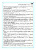
VBQ-MGB17017
Brand: Tarrington House Pages: 4

CBIE622
Brand: Everdure Pages: 13
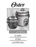
4722
Brand: Oster Pages: 20

BAT-18A11
Brand: Kitchen move Pages: 6

BC30ITB
Brand: Baumatic Pages: 25

SIG 531
Brand: Parkinson Cowan Pages: 56

RJGR
Brand: Jade Pages: 16

BO743WI
Brand: Bompani Pages: 60

RK 2220 CB
Brand: BOMANN Pages: 44

EW32
Brand: Hotpoint Pages: 44

ME301JS
Brand: Thermador Pages: 1

177GRCS20
Brand: Galaxy Equipment Pages: 8

SLIPIN
Brand: Parkinson Cowan Pages: 40

CG365DW Series
Brand: Fisher & Paykel Pages: 26

I6ESH2E/KZ
Brand: Indesit Pages: 76

IDV 2660n
Brand: Concept2 Pages: 64

IV1Z
Brand: Vigan Mammoth Pages: 44


