background image

2012-07-02

Assembly instruction
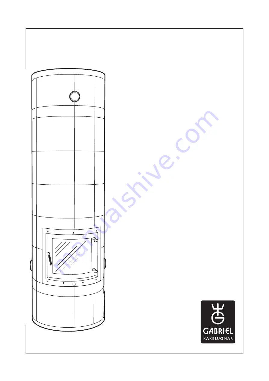
 

STUDIO


tiled stove


(series 400)

Model....................................

Content

Tests and approvals ............................ 2
Explanation of symbols / foreword ...... 3

Body 

Preparations ...................................... 4
Important measurements...................... 5
Overall installation sequence ............... 6
Assembly ..................................... 7-17

Tiles and cassette

Tiling preparation and assembly ... 17-18
Tiling plan ....................................... 19
Cassette installation ..................... 20-23
Fan installation ................................ 23

Summary of Contents for STUDIO 400 Series

Page 1: ...tent Tests and approvals 2 Explanation of symbols foreword 3 Body Preparations 4 Important measurements 5 Overall installation sequence 6 Assembly 7 17 Tiles and cassette Tiling preparation and assemb...

Page 2: ...imney sweep before building the stove Weight from 1300 to 1800 kg Bearing support is required EU declaration of conformity Products covered by this declaration Product type Slow heat release appliance...

Page 3: ...reas for sawing and placing of mortar are marked with a pen Control measurement Shows important measurements during assembly Trowel Shows where the clay mortar is placed Rendered areas Shows the areas...

Page 4: ...mm 415 mm min 75 mm 415 mm Base block 680 mm Preparations In a corner Against a straight wall In a corner Against a straight wall Combustible wall Combustible wall Combustible wall Combustible wall Me...

Page 5: ...1 8 8 8A 8A 9 10 10 10 10 10 10 11 13 13 13 12 12 min 75 mm min 75 mm min 75 mm Base block 680 mm No joints 1 17 shows the numbers of all parts see page 6 Important measurements STUDIO Corner wall po...

Page 6: ...GABRIEL KERAMIK AB 6 STUDIO Start A 7 7 7 6 5 5 4 3 2 1 17 16 15 14 7 7 7 7 7 7 7 7 7 10 10 9 8A 8A 8 8 10 10 10 10 13 13 13 12 12 11 Overall installation sequence...

Page 7: ...ion distance to the wall is kept Level vertically and horizon tally The opening can be directed at right Check the distance to the wall min 75 mm Before starting the assembly make sure that the suppor...

Page 8: ...orrectly Set the outer block 3 with mortar The opening shall face the 45 marking on the floor step 1 Seal with insulation where indicated Set the outer block 4 with mortar level the soot hole with the...

Page 9: ...nd horizontally Push the firebox block backwards as much as possible Place the insu lation and pull the firebox block back to lock the indsulation Set the second firebox block 8 on top of the first on...

Page 10: ...r Check that the height is within the tolerane 508 mm For a better joint wipe the contact surfaces with a squeezed sponge then brush with a wet radiator brush Set the third firebox block 8A on top of...

Page 11: ...he blocks Level vertically and horizontally Cut off the insulation Before continuing above the firebox opening construct a prop to sup port both the outer ring and the firebox top block as shown in th...

Page 12: ...not be in contact Level vertically and hori zontally Check the control measurements see page 5 For a better joint wipe the contact surfaces with a squeezed sponge After wards gently brush the mortar j...

Page 13: ...vel vertically and horizontally Seal with 2 3 mm insulation Set the flame protection block 13 with mortar Level vertically and horizontally Set the outer ring 7 in mortar Level vertically and horizont...

Page 14: ...7 1980 mm 7 20 21 22 Set the outer ring 7 with mortar Level vertically and horizontally Assembly Set the outer ring 7 with mortar Level vertically and horizontally Set the outer ring 7 with mortar Lev...

Page 15: ...k and the flame protection block Fix the insulation in the mortar string The insulation creates an expan sion gap aginst the divider block allowing the inner core to move vertically Set the divider bl...

Page 16: ...top lid 14 with mortar Level vertically and horizontally Lay mortar over the damper and the pipeattachment Set the Leca blocks 16 with mortar The inside of the blocks shall be rendered with clay morta...

Page 17: ...nel surfaces also the downside of the top lid when it is installed Top connected chimney Set the top lid 17 with mortar and make sure it is in level with the underlying flue gas hole Side connected ch...

Page 18: ...thed trowel For the best result a joint width of 2 3 mm is rec ommended Wooden wedges recommended Seal with adhesive between tiles and body at the firebox and the soot holes Start tiling from the bott...

Page 19: ...GABRIEL KERAMIK AB STUDIO 19 Kakelsats Studio Decor steel band 50 mm 310 x 210 mm 100 x 210 mm Decor steel band 30 mm Tiling plan...

Page 20: ...ace the enclosed rockwool sheet Cut out a square hole the same size as the hole in the firebox plate as indicated Fit in the cassette so that the steel flanges round the cassette are inside the tiles...

Page 21: ...ion Pass the flexible tube through the cassette bottom and fit it over the connecting flange Fasten the flange plate Mount the damper in the bottom of the cassette do not forget the cotter pins Make s...

Page 22: ...t silicon seal Pull out the cassette approx 20 mm and apply silicon just inside the edge around the brass frame then push the cassette back in Even the seal with a wet finger dipping the finger into w...

Page 23: ...ar in as it will restrict the inlet convection air flow to the cassette Press the fan carefully into the pre cut hole in the sealing block Note The fan must be moun ted so that air is sucked into the...

Page 24: ...GABRIEL KERAMIK AB www gabrielkakelugnar se Tel 46 0 499 233 00...

Reviews: