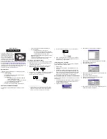
background image

TR-150 

Vehicle/Asset Tracker 

User Manual 

Version 

0.2.3 


Summary of Contents for TR-150

Page 1: ...TR 150 Vehicle Asset Tracker User Manual Version 0 2 3 ...

Page 2: ...etup 18 5 5 SMS Tracking commands and Configuration for SMS Call Center software developer 20 6 Operating the device 21 6 1 Turn on Turn off 21 6 2 Tracking Monitoring TR 150 by SMS 22 SMS Report functions _ Immediate Report 23 SMS Report functions _ Period Report 24 SMS Report functions _ Stop Report 25 6 3 Geofence 26 6 4 Voice monitor function 29 6 5 The format of return SMS from TR 150 30 6 6 ...

Page 3: ...s z SiRF Star III LT GPS chipset SiRF latest flagship performance lowest power consumption GPS chipset z Combination of GPS GSM wireless network z Durable and water resistant GPS tracker z Easy to install or hide in the car to perform tracking No external wires needed z Ideal application for vehicle tracking and equipment assets monitoring z Optional external antenna for GPS reception z Rechargeab...

Page 4: ...um WGS 84 Hot start 1 sec average Warm start 35 sec average Cold start 35 sec average Altitude Limit 18 000 meters 60 000 feet max Velocity Limit 515 meters second 1000 knots max Acceleration Limit Less than 4g Jerk Limit 20 m sec3 Operating temperature 20 to 55 C Antenna Type GPS patch antenna Dimension 86 7 48 9 32 5 mm Battery 2100mA rechargeable Li ion battery LED indicator For Charging GPS GS...

Page 5: ...TR 150 page 5 3 Start up 3 1 Accessories TR 150 AC charger USB Cable Battery Car charger Mounting bracket with magnet optional ...

Page 6: ...TR 150 page 6 3 2 Install SIM card and Battery z Use a coin or screwdriver to loosen the screw on back cover z Lift the back cover and remove it as the direction shown ...

Page 7: ...as the direction marked OPEN on it z Slide in the SIM card with its metal contacts facing down and the cut corner at the top left z Plug the battery connector into socket Be aware that the red wire is on the top side when you plug in the connector ...

Page 8: ...y Before your first time using of TR 150 please connect it with AC power adapter for battery charging under the power off condition The included battery is specially designed for TR 150 Please do not use other type of battery otherwise it will damage the device If you need to change the battery for TR 150 please contact you local dealer ...

Page 9: ...TR 150 page 9 3 4 TR 150 with magnetic holder z Insert the TR 150 with the Power button side facing out z Push TR 150 into the holder until it clicks in position ...

Page 10: ...k of magnetic holder there are 4 circular magnets which you can use it for attaching TR 150 onto the metal material of vehicle or machine z To remove TR 150 slightly push the both sides of holder outward and slide out the TR 150 ...

Page 11: ...TR 150 page 11 4 Hardware Overview 4 1 Appearance 1 Power button 2 SOS button 3 Indicators 4 USB connector 5 Microphone 6 External antenna connector ...

Page 12: ...k search in progress ongoing user authentication or network login in progress LED is blinking quickly about once per second y In standby mode LED is blinking slowly once per 3 seconds 2 GPS LED The LED is steady on when it is fixing the location The LED will be blinking when TR 150 s location is fixed 3 Status LED y When battery low LED steady on y When enter setup mode LED steady on y Press power...

Page 13: ...xternal GPS antenna 4 3 DIP switch Note The Factory default of DIP switch is set to OFF Switch 1 sets to ON Enable the Auto On feature When external power is connected the device will auto on When remove external power the device is off Switch 2 sets to ON All LEDs except Status LED go off to perform secret tracking Status LED flashes as usual except battery low In another word Status LED is not o...

Page 14: ...ows is Vista version please double click to open PL2303_USB_Driver_for_Windows_Vista folder and double click on PL 2303 Vista Driver Installer exe to begin installation Follow the instruction to complete the installation process 5 If your Windows is XP or 2000 version please double click to open PL2303_USB_Driver_for_Windows_2000_XP folder and double click on PL 2303 Driver Installer exe to begin ...

Page 15: ... Software button to install the Call Center program 2 Follow the instruction to complete the installation process 3 After the installation is completed You will see the icon TR150 Call Center appears on desktop Double click on this icon to start TR150 Call Center program ...

Page 16: ...TR 150 page 16 5 3 Call Center Menu ...

Page 17: ...after you have already set 5 users please delete an existing one first Device TR150 Setup When a TR 150 is connected to your PC you can do the basic setup for TR 150 Map View Tracking Points Check this item to mark returned location in the Google Map When you receive the latest data report from TR 150 it will automatically update the point on Google Map Only for SMS Tracking function Map Export KM...

Page 18: ... on the power of TR 150 The status LED will light on red indicating it has already entered the setup mode 4 Start Call Center program 5 Click Device TR150 Setup to select the COM port If you are not sure about which COM port to use please click Scan COM Port button to automatically scan it Then click Setup button to enter setup window ...

Page 19: ... GPS fixing is not achieved in time it will close GPS and send back the previous location info Default Report Mode Setting Item Description Default Report Mode User can configure TR 150 to perform the Default Report Mode There are 3 report modes immediate report period report stop report standby When you select some report mode the unavailable item will be disabled After power on the device TR 150...

Page 20: ...ll Center software developer You can connect one TR 150 to PC and use GlobalSat PC software Call Center to send SMS tracking commands and SMS configurations to control TR 150 It can help Call Center service providers to evaluate TR 150 and build their own SMS Call Center efficiently Please refer to SMS_Call_Center_software_Development_manual_VX X_EN doc for details ...

Page 21: ... the better GPS signal when you turn on the device NOTICE If it did not finish the successful fix after turned on it may be difficult to get fixed in the weak signal area or on the move After it is turned on or received the report command TR 150 starts the GPS fixing process User can define the maximum time allowable for this GPS fixing process If TR 150 finishes the GPS fixing within the time it ...

Page 22: ...latitude C longitude latitude radius meter In_or_Out Report_Interval Number_of_Reports Report_Format Return_Phone_Number 4 IMEI OK 6 Voice monitor 6 IMEI Return_Phone_Number Note If return phone number is empty TR will call back to Caller ID 6 IMEI OK Note 1 Data Report Format Report_Format 0 Æ Format0 Report_Format 1 Æ Format1 Please refer to description in this chapter later 2 Return Phone Numbe...

Page 23: ...on When the GPS position is fixed it will again return the position data Report type Format Return message 0 Immediate report 0 IMEI Report_Format Return_Phone_Number 0 IMEI OK The description of SMS Format Description 0 Start sign and function code IMEI IMEI of TR Report_Format Ask TR to return message by Format0 or Format1 see description below Return_Phone_Number The report message will be sent...

Page 24: ...eport_Format Return_Phone_Number 1 IMEI OK The description of SMS Format Description 1 Start sign and function code IMEI IMEI of TR Report_Interval Time interval of sending data report The unit is second Number_of_Reports How many reports will be sent Number_of_Reports 0 Æ continuous report Number_of_Reports X Æ X times report Report_Format Ask TR to return message by Format0 or Format1 see descri...

Page 25: ...Report type Format Return message 2 Stop 2 IMEI Return_Phone_Number 2 IMEI OK The description of SMS Format Description 2 Start sign and function code IMEI IMEI of TR Return_Phone_Number The report message will be sent to the phone number No report message End sign Example Send Stop command to disable data report and make GPS off Return message will be sent to 626123456 2 355632000166323 626123456...

Page 26: ...adius meter In_or_Out Report_Interval Number_of_Reports Report_Format Return_Phone_Number 4 IMEI OK The description of SMS Format Description 4 Start sign and function code IMEI IMEI of TR R longitude latitude longitude latitude C longitude latitude radius meter Boundary information R rectangle Æ Follow by two longitudes latitudes C circular Æ Follow by one longitude latitude and one radius In_or_...

Page 27: ...Out Report_Interval Number_of_Reports Report_Format Return_Phone_Number SMS3 4 IMEI C longitude latitude radius In_or_Out Report_Interval Number_of_Reports Report_Format Return_Phone_Number If user uses numerous SMS in one setting the IMEI In_or_Out Report_Interval Number_of_Reports Report_Format Return_Phone_Number must be the same between each SMS If above parameters are not the same between SMS...

Page 28: ...ndary includes one rectangle two longitudes latitudes Æ 24 00000 121 00000 25 00000 122 00000 and two circles one longitude latitude is 26 00000 123 00000 and radius is 1000 meter the other longitude latitude is 27 00000 124 00000 and radius is 1500 meter When TR is out boundary sending format1 10 times 120 sec interval alarm message to 626123456 SMS1 4 355632000166323 R 24 00000 121 00000 25 0000...

Page 29: ... message 6 Voice monitor 6 IMEI Return_Phone_Number 6 IMEI OK The description of SMS Format Description 6 Start sign and function code IMEI IMEI of TR Return_Phone_Number TR will call back to this phone number End sign Note If return phone number is empty TR will call back to Caller ID Example User send voice command and make TR call back to 626123456 6 355632000166323 626123456 ...

Page 30: ...tion report Name 2006 9 15 10 20 39 24 99653 121 48769 GPS fixed Format1 IMEI Status GPS_Fix Date Time Longitude Latitude Altitude Speed Heading Number_of_Satellites_In_Use HDOP Example 353857014816785 2 3 280807 035825 E12129 2616 N2459 7918 97 2 0 13 142 31 04 2 4 The description of Format1 Format Value Note Command Head IMEI The number of IMEI Status 0 1 3 0 Immediate report 1 Period report 3 T...

Page 31: ...6 SOS function Presses the SOS Button the status LED will flash 3 times to indicate that the button is activated TR 150 will immediately send out an emergency message along with its GPS report to 3 preset phone numbers ...

Page 32: ... Enable or disable SMS Default Return Phone Number Enable_SMSDefaultReturnPhoneNumber 0 Æ Disable Enable_SMSDefaultReturnPhoneNumber 1 Æ Enable Maximum_GPS_Fixing_Time If GPS is not fixed within the time it returns previous location and close GPS The unit is minute Number_of_Reports Set how many report will be sent Number_of_Reports 0 Æ continuous report Number_of_Reports X Æ X times report Report...

Page 33: ...0 Æ Disable 1 Æ Enable SMSDefaultReturnPhoneNumber In the SMS tracking commands immediate report period report stop report Geofence if the field Return_Phone_Number is empty TR 150 will send data report to this SMSDefaultReturnPhoneNumber Return_Phone_Number The confirmed SMS sent to the phone number to indicate the setting is successful End sign Example To configure SMS default return phone numbe...

Page 34: ...EI IMEI of TR 2 Setting code for Maximum GPS fixing time Maximum_GPS_Fixing_Time The time that allows for GPS fixing If GPS fixing is not achieved within the time it will close GPS and send back the previous location info Return_Phone_Number The confirmed SMS sent to the phone number to indicate the setting is successful End sign Example To configure Maximum GPS fixing time to 5 minutes and send c...

Page 35: ...e number for default report mode Return_Phone_Number The confirmed SMS sent to the phone number to indicate the setting is successful End sign Note The configuration is for default report mode Immediate Period or Stop settings In immediate and stop settings some fields are unnecessary please leave these fields empty and separate them by a comma Please see following examples for detail Example Imme...

Page 36: ...escription 7 Start sign and function code IMEI IMEI of TR 4 Setting code for SOS numbers SOS SOS numbers Return_Phone_Number The confirmed SMS sent to the phone number to indicate the setting is successful End sign Example Configure SOS1 SOS2 and SOS3 as 616123456 717123456 818123456 and send confirmed SMS to 626 123456 7 355632000166323 4 616123456 717123456 818123456 626123456 ...

Page 37: ...talled and used in accordance with the instructions may cause harmful interference to radio communications However there is no guarantee that interference will not occur in a particular installation If this equipment does cause harmful interference to radio or television reception which can be determined by turning the equipment off and on the user is encouraged to try to correct the interference ...

Page 38: ... model phone as reported to the FCC when tested for use at the ear is 0 758 W kg for GSM850 0 735 W kg for PCS1900 and when worn on the body as described in this user guide is 0 21 W kg for GSM850 0 223 W kg for PCS1900 Body worn measurements differ among phone models depending upon available enhancements and FCC requirements While there may be differences between the SAR levels of various phones ...

Reviews: