background image

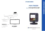
Summary of Contents for FCV-587

Page 1: ......

Page 2: ...s product according to local regulations for the disposal of industrial waste For disposal in the USA see the homepage of the Electronics Industries Alliance http www eiae org for the correct method o...

Page 3: ...t for service Do not maneuver the vessel based on the depth indication alone Grounding can result Do not disassemble or modify the equipment Fire electrical shock or injury can result Use the proper f...

Page 4: ...fuels and oils away from the cable Locate cable in a safe place Do not paint the cable The sheath of the cable is made of chloroprene rubber or polychloride vinyl For this reason do not paint the cab...

Page 5: ...9 1 19 4 How to set destination waypoint 20 1 20 Setting Up Nav Data Displays 20 1 20 1 Nav data displays 20 1 21 Menu Description 21 2 SYSTEM MENU 26 2 1 How to Display the System Menu 26 2 2 Range M...

Page 6: ...V 627 587 are Bright color LCD gives excellent readability even in broad daylight Waterproof construction permits installa tion on open bridge Automatic mode automatically adjusts the set to provide t...

Page 7: ...Electric Reel 520 5PSD 520 5MSD 520 PLD 525 5PWD 525T PWD 525T BSD 525T LTD 12 525T LTD 20 525STID MSD 525STID PWD SS60 SLTD 12 SS60 SLTD 20 DISPLAY UNIT CV 587 E 12 24 VDC 1 Radio transmitter of SHI...

Page 8: ...s function key programming window 7 GAIN Push Opens Auto Gain setting window Rotate Manually adjusts gain 8 MODE Selects display mode 9 BRILL Short press Turns on power opens the Brill adjustment wind...

Page 9: ...ange 1 4 Display Mode 1 Rotate the MODE knob to open the mode setting window which is displayed for six seconds 2 Rotate the MODE knob again to select the display mode desired The screen re lated to t...

Page 10: ...om dis play go to the Range menu see section 2 2 Note 2 To show or hide the zoom marker go to the Display menu Picture advance speed Display mode Range Gain Minute marker Each bar equals 30 sec Data b...

Page 11: ...opriate sensor Two nav data displays are available Nav Data 1 or Nav Data 2 and you may select which to use on the Display menu The de fault settings are as follows NAV1 Two data display SPEED STW WIN...

Page 12: ...ect the range Japanese unit of depth measurement Note Basic ranges may be preset as de sired For further details see section 2 2 4 Press the ENTER key Note The range mode indication which ap pears at...

Page 13: ...e If you selected Fishing or Cruising you can apply an offset to the gain at step 3 To apply no offset go to step 4 For Off do steps 4 and 5 3 Press W or X setting range 5 to 5 to apply an offset Pres...

Page 14: ...a set ting press the MENU ESC key instead of the ENTER key 7 To select another menu press the MENU ESC key or W The cursor yel low moves to the main menu 8 Press the MENU ESC key to close the menu No...

Page 15: ...t tom and use a slow advance speed to moni tor a smooth bottom 1 Open the menu select Sounder and press the ENTER key 2 Select Pic Advance and press the EN TER key 3 Select picture advance speed desir...

Page 16: ...f the interference rejector when no interference exists so as not to miss weak echoes from small targets 4 Press the MENU ESC key twice to close the window 1 12 How to Reduce Low Level Noise Low inten...

Page 17: ...scope Display The A scope display shows echoes at each transmission with amplitudes and tone pro portional to their intensities on the right 1 3 of the screen The display shows strong echoes with stro...

Page 18: ...tensity depends on fish species When the fish length differs between the in dicated length and the actual length you can compensate the difference on the Calib menu see section 2 6 ACCU FISHTM is inop...

Page 19: ...imated length of the fish Note To hide the fish symbol select Off at step 4 and press the ENTER key Note You can select which frequency display to show the fish symbols and fish information with Symbo...

Page 20: ...0 knots or less This feature uses the range from the boat s draft therefore enter the ship s draft See page 26 Be sure that the transducer is mounted straight Otherwise the bottom discrimina tion disp...

Page 21: ...The bottom type alarm alerts you when the bottom type rock sand mud gravel match es the bottom type selected Available when the bottom discrimination display is active The bottom alarm alerts you whe...

Page 22: ...o to step 2 For other choices go to step 6 2 Select From under Fish Type and press the ENTER key 3 Set the minimum fish length and press the ENTER key 4 Select Span be low Fish Type and press the ENTE...

Page 23: ...lect From and press the ENTER key 3 Set the starting depth and press the ENTER key 4 Select Span and press the ENTER key 5 Set the width of the alarm and press the ENTER key 10 Press the MENU ESC key...

Page 24: ...he ENTER key 2 Select Inside or Outside as applica ble and press the ENTER key 3 Select Radius and press the ENTER key 4 Enter the alarm radius and press the ENTER key To disable the alarm select Off...

Page 25: ...desired Up down for verti cal movement left right for horizontal movement Picture advancement is stopped until step 3 is completed 3 Press the MARK or ENTER key to regis ter the position set at step 2...

Page 26: ...ess the ENTER key 2 Select WPT List and press the ENTER key 3 Select the waypoint to edit and press the ENTER key 4 Select the item desired and press the EN TER key 5 Edit data as appropriate 6 Press...

Page 27: ...be low Note 1 When a data is lost 30 sec the dis play shows at the lost data s location Note 2 A triducer w speed sensor is required to display distance distance run and speed through the water A trid...

Page 28: ...e ENTER key White Marker Display the selected echo color in white WPT XTE Cross track error Rng Range to WPT Brg Bearing to WPT Cse Course STBD Starboard PORT Port STBD 01 Cross track error Speed over...

Page 29: ...of gain reduction against short range echoes Note Auto gain must be disabled to use the TVG Smoothing Smooth echo presentation when enabled Turn smoothing on when ech oes appear spotty or jagged Bott...

Page 30: ...play is active Temp Graph Turn the water temperature graph on or off The temperature scale range is 16 F in Narrow 40 F in Wide Re quire water temperature data Window Size Adjust the display area of t...

Page 31: ...u can select multiple indi cations in which case they are displayed alter nately every four seconds default setting 1 Select Nav Data1 and press the ENTER key 2 Select Data Box1 and press the ENTER ke...

Page 32: ...rature indication Select Own to use the water temperature data from the wa ter temperature sensor connected to this unit or NMEA to use the water temperature data from a navigator Speed Source Select...

Page 33: ...is the largest setting of Range 1 to Range 8 of Manual Range In case the sea bottom is deeper than the largest setting of Auto Range set the setting of Range 1 to Range 8 deeper than the sea bottom Z...

Page 34: ...NM km and SM 2 6 Calib Menu Draft The default depth display shows the distance from the transducer If you would rather show the dis tance from the sea surface set your ship s draft Gain ADJ HF Gain A...

Page 35: ...o low a setting may prevent display of the bottom echo Bottom Level In the default bottom level setting 0 the equipment judges consecu tive strong echoes to be bot tom echoes If in that setting the de...

Page 36: ...partner ship in the Tankenmaru system via a radio transmit ter Pic Sync Display or don t display the same video signal on your display unit and a part ner s display unit Yes Display the same video si...

Page 37: ...er or anti fog solution on the LCD as they can strip the coating on the LCD 3 3 Transducer Main tenance Marine life on the face of the transducer will result in a gradual decrease in sensitivity Check...

Page 38: ...tomatically turned off WARNING Use the proper fuse Use of a wrong fuse can result in fire and damage the equipment If then check the screen is blank adjust the brilliance neither echo nor fixed range...

Page 39: ...se rotation Press the knob The knob s corresponding on screen circle lights in red if the knob is normal Re lease hold and the circle turns white How to check MODE knob Rotate the knob The correspondi...

Page 40: ...restore default menu settings and re set the odometer trip distance indication as follows 1 Open the menu and select Restore un der System and press the ENTER key 2 Select Default Setting or Odometer...

Page 41: ...sher Type M4 Code No 000 167 455 10 4 pcs Spring Washer Type M4 Code No 000 167 405 10 4 pcs Threaded Rod Type M4 50 Code No 000 162 679 10 4 pcs Name Type Code No Qty Remarks Display Unit CV 587 E Se...

Page 42: ...04 02M 001 090 910 2 m Speed Tem perature Sensor ST 02MSB 000 137 986 01 Thru hull mount metal ST 02PSB 000 137 987 01 Thru hull mount plastic Temperature Sensor T 04MSB 000 026 893 Thru hull mount T...

Page 43: ...ad screws on the rear of the display unit to remove the bracket cover and the cover sponge FCV 587 only 3 Set the flush mounting sponge supplied to the display unit 4 Screw four threaded rods supplied...

Page 44: ...side to keep the transducer face parallel with the water line Fabricate the fairing block as shown below and make the entire surface as smooth as possible to provide an undis turbed flow of water arou...

Page 45: ...se turbulence is created by the propeller ahead of the transducer DO NOT overtighten screws they may be damaged 525 5PWD mounting locations Select the installation method depending on the rise angle o...

Page 46: ...ocations considering the four points mentioned below You will finalize the mounting location through some trial and error later Mount the transducer at a location 1 2 to 1 3 of the length of the boat...

Page 47: ...ghen the inside of the hull where the transducer is to be mounted 4 Wipe off any sandpaper dust from the face of the transducer 5 Dry the face of the transducer and the hull Coat the transducer face a...

Page 48: ...d tur bulence free water Mount the sensor close to the centerline of the boat On slower heavier displacement hulls positioning it farther from the centerline is acceptable Allow adequate space above t...

Page 49: ...d for a standard 13 transom angle 11 18 angle No shim is required Skip to step 3 in Adjustments Other angles The shim is required Skip to step 2 of Adjustments If you do not know the transom angle tem...

Page 50: ...slots slide the sensor up or down to provide a projection of 3 mm 1 8 Tighten the screws Vertical adjustment and cable routing Attaching the sensor to the bracket 1 If the retaining cover near the to...

Page 51: ...e 5 If a hole has been drilled in the transom open the appropriate slot in the transom cable cover Position the cover over the cable where it enters the hull Mark the two mounting holes 6 At each of t...

Page 52: ...k the boat 2 Make a hole of approx 51 mm diameter in the mounting location 3 Unfasten the locknut and remove the sen sor section 4 Apply marine sealant to the flange of the sensor The height of the co...

Page 53: ...h positive polarity DC power and the fish finder is grounded to the hull external equipment cannot be connected directly to the fish finder if the signal line of the equipment is connected to ground E...

Page 54: ...sducer Tape connectors with vulcanizing tape and then vinyl tape to waterproof them Bind tape ends with cable ties to prevent tape from unraveling Transducer 50B 6 6B 50kHz 200kHz SHIELD BLK RED TB2 1...

Page 55: ...D MSD or 525STID PWD skip this procedure 1 Select Type from the Installation menu and press the ENTER key Data Priority Latitude Longitude GNS GGA RMC RMA GLL Course true VTG RMC RMA Course magnetic V...

Page 56: ...finder NMEA0183 Select NMEA0183 version of nav equipment connected to 12 24 VDC NMEA port among Ver 1 5 Ver 2 0 and Ver 3 0 NMEA Port The NMEA terminals in the 12 24 VDC NMEA port can function as inp...

Page 57: ...Requires FU RUNO TLL enabled device Port Monitor Port Monitor shows the data sentences input to the 12 24 VDC NMEA port Press the ENTER key to display the latest data sentence information To display...

Page 58: ...On Bottom Zone TX Power Auto 10 100 TX Rate 1 10 S Max 10 ACCU FISH Off On Fish Info Off Fish Size Depth Info Size Small Large Fish Symbols Off Striped Solid Circle Square Symbols Area Dual HF LF Bott...

Page 59: ...Range 5 7 4000 ft 200 ft Range 6 7 4000 ft 400 ft Range 7 7 4000 ft 600 ft Range 8 7 4000 ft 1000 ft Zoom Range 7 4000 ft 15 ft BLRange 7 30 ft 15 ft Key FUNC Key Pic Advance Shift Interference Clutt...

Page 60: ...vel 100 100 0 Demo Demonstrate Off Demo1 Demo2 Demo 3 Demo 4 Tests Diagnostic Test LCD Test Restore Default Setting Yes No Odometer Yes No Rejector Off On Area 4 5 9 8 ft 4 5 ft Tankenmaru Output Off...

Page 61: ...steel housing must be isolated from a metal hull to prevent electrolytic corrosion Use the isolation bushing supplied CAUTION Never use solvents Cleaners fuel sealant paint and other products may cont...

Page 62: ...tersink tool installing SS565 Sandpaper Mild household detergent or weak solvent such as alcohol File installation in a metal hull Marine sealant suitable for below waterline Slip joint pliers install...

Page 63: ...spacer if there is insufficient space to tighten the nut or it is within 11 mm 1 2 of the top of the housing Stainless steel housing in a metal hull Be sure the washer contacts the hull Do not tighte...

Page 64: ...le on page AP 5 3 From inside the hull using the appropriate size hull interior hole saw cut through the inner skin and most of the core The core material can be very soft Apply only light pressure to...

Page 65: ...re is any petroleum residue inside the hull remove it with either mild household detergent or a weak solvent alcohol before sanding Record the information found on the cable tag for future reference P...

Page 66: ...interference separate the transducer cable from other electrical wiring and the engine Coil any excess cable and secure it in place with cable ties to prevent damage 2 Refer to the instrument owner s...

Page 67: ...ketones can attack many plastics possibly damaging the sensor Reapply anti fouling paint every 6 months or at the beginning of each boating season Replacement Sensor Parts The information needed to o...

Page 68: ...elow for optimal product performance and to reduce the risk of property damage personal injury and or death WARNING Always wear safety goggles and a dust mask when installing WARNING Below the waterli...

Page 69: ...pencil 8 Using a 3mm or 1 8 drill bit drill a pilot hole s at the marked locations 10mm 3 8 deep 9 Apply marine sealant to the threads of the screw s to prevent water from seeping into the transom 10...

Page 70: ...0 200 300 2 to 1 200 ft 15 30 60 120 200 400 600 1 000 7 to 4 000 fm 3 5 10 20 40 80 100 150 1 to 650 pb 3 5 10 20 50 100 150 200 1 to 800 HR 4 8 15 30 50 100 150 200 1 to 700 Japanese unit of depth m...

Page 71: ...RMA RMB RMC VHW VTG XTE ZDA Output DBS DBT DPT MTW RMB VHW TLL by key operation External data required 4 POWER SUPPLY FCV 627 12 24 VDC 1 1 0 5 A FCV 587 12 24 VDC 1 2 0 6 A 5 ENVIRONMENTAL CONDITION...

Page 72: ...4 5 2 55 10 056 6 10 6 4 5 2 1 7 06 75 1706 0 6 2 6 12 4 614 5 07 1 12 4 614 5 7 12 4 614 5 7 15 A 1 8 0 1 7 6 0 5 4 26 10 1 3 6 70 6 52 70 6 8 52 4 2 465 52 52 4 2 465 52 5514 5 2 5514 5 2 056 6 10 6...

Page 73: ...7 Nov 2013 H MAKI D 1...

Page 74: ...18 Nov 2013 H MAKI D 2...

Page 75: ...D 3 13 Jan 2012 Y NISHIYAMA...

Page 76: ...D 4 13 Jan 2012 Y NISHIYAMA...

Page 77: ...D 5 12 Mar 2015 H MAKI...

Page 78: ...0V NC SPD0V TDID0V ST SHIELD TD_ID 7 8 9 10 1 2 3 4 5 6 IV 1 25sq 1 525 5PWD 520 5PSD 520 5MSD MJ A6SRMD XDR MJ A10SPF 02S4147 0 2m 2 SPD TEMP 12V P1 XDR M XDR P XDR SHIELD TEMP0V NC SPD0V TDID0V ST S...

Page 79: ...Gain adjustment 5 GAIN knob 5 H Header info 24 Header scale 24 HF display 2 I Interference 9 K Key menu 26 L Language menu 26 LCD test 33 LF display 2 M Maintenance 30 Marker zoom display 4 MODE knob...

Page 80: ...cient Otherwise the invoice with serial number name and stamp of the dealer and date of purchase is shown For the Onboard Warranty your FURUNO certified dealer will take care of all registrations 5 Wa...

Page 81: ...or its authorized dealer at the time of request for warranty service This warranty is valid for installation of products manufactured by Furuno Electric Co hereafter FURUNO Any purchases from brick a...

Page 82: ......

Page 83: ......

Reviews: