background image

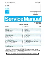
20” LCD Color Monitor                                         FSC P20W-3 

-1- 

 
Service  

Service


Service


Horizontal Frequency 

                                                                                  30kHz – 82kHz 

      TABLE OF CONTENTS                                                                         

Description


Page      Description                                                              Page 


SAFETY NOTICE


  ANY PERSON ATTEMPTING TO SERVICE THIS CHASSIS MUST FAMILIARIZE HIMSELF WITH THE 

CHASSIS AND BE AWARE OF THE NECESSARY SAFETY PRECAUTIONS TO BE USED WHEN SERVICING 

ELECTRONIC EQUIPMENT CONTAINING HIGH VOLTAGES. 

Table Of Contents.......…….................……...........…........1

Revision List.…........................………................……......2 

Important Safety Notice.………….…..................……......3

1.Monitor Specification..............................………........4  

2.LCD Monitor Description…………………………….......5

3.Operation Instruction…………...............……...........6

3.1.General Instructions...........................…...........6

3.2.Control Button…………….…..............……...............6

3.3 Adjusting the Picture...........................…............7

4.Input/Output Specification............……………............10

4.1.Input Signal Connector............………….................10

4.2.Factory Preset Display Modes.........................12

4.3.Power Supply Requirements.........................12

4.4.Panel Specification.....………………..................13

5.Block Diagram…….…...................…………................15

5.1.Software Flow Chart……………………….............15

5.2.Electrical Block Diagram…………..…..….......17

6.Schematic……………...............................….....18

6.1.Main Board.............................…................18

6.2.Power Board....……....................................27

7.PCB Layout..…………..........................................29

7.1.Main Board………........................................29

7.2.Power Board....……....................................32

7.3.Key Board……………………………………………35

8.Maintainability……….......................................36

8.1.Equipments and Tools Requirement...............36

8.2.Trouble Shooting…………..............................36

9. White-Balance, Luminance adjustment.............42

10.Exploded View.....….......….....................44

11.BOM List….....................................................46

12.Different Parts List….............................................61

CAUTION: USE A SEPARATE ISOLATION TRANSFOMER FOR THIS UNIT WHEN SERVICING 

Summary of Contents for FSC P20W-3

Page 1: ...ction 6 3 1 General Instructions 6 3 2 Control Button 6 3 3 Adjusting the Picture 7 4 Input Output Specification 10 4 1 Input Signal Connector 10 4 2 Factory Preset Display Modes 12 4 3 Power Supply Requirements 12 4 4 Panel Specification 13 5 Block Diagram 15 5 1 Software Flow Chart 15 5 2 Electrical Block Diagram 17 6 Schematic 18 6 1 Main Board 18 6 2 Power Board 27 7 PCB Layout 29 7 1 Main Boa...

Page 2: ... LCD Color Monitor FSC P20W 3 2 Revision List Revision Date Revision History TPV Model Name A00 Jul 31 2007 Initial Release TA7GM3DBIWM7DC A01 Nov 02 2007 The Second Release TA7GM3DBIWM78C TA7AM3DBIW1MDC ...

Page 3: ...characteristics may create shock fire or other hazards Under no circumstances should the original design be modified or altered without written permission from AOC AOC assumes no liability express or implied arising out of any unauthorized modification of design Servicer assumes all liability FOR PRODUCTS CONTAINING LASER DANGER Invisible laser radiation when open AVOID DIRECT EXPOSURE TO BEAM CAU...

Page 4: ...ain Dimensions W x H x D Packed Monitor 561 0mm x 265 0mm x438 0mm Monitor 7 0 kg incl Stand Weight Packed Monitor 9 57 kg Power consumption typical without audio 42 W Operating temperature 5 C 40 C Operating Humidity 20 85 Storage Temperature 5 C 40 C Storage Humidity 5 85 Environmental Condition Transport Temperature 20 C 60 C Storage Humidity 15 98 Safety compliance CE EN60950 cUL CSA CCC EMC c...

Page 5: ...ol logic brightness control logic and DDC The power board will provide the AC to DC voltage to drive backlight and the main board chips each voltage Video signal DDC Power board Include Inverter and Adapter Flat Panel and CCFL backlight Main Board Key board RS232 Connector For white balance adjustment in factory mode HOST Computer CCFL Drive AC IN 100V 240V Monitor Block Diagram ...

Page 6: ...rol buttons are located in the front of the monitor By changing these settings the picture can be adjusted to your personal preferences The power cord should be connected Connect the video cable from the monitor to the video card Press the power button to turn on the monitor the power indicator will light up 3 2 Controls and Buttons External Controls ...

Page 7: ...20 LCD Color Monitor FSC P20W 3 7 3 3 Adjusting the Picture To set the OSD menu perform the following steps ...

Page 8: ...20 LCD Color Monitor FSC P20W 3 8 ...

Page 9: ...20 LCD Color Monitor FSC P20W 3 9 ...

Page 10: ...20 LCD Color Monitor FSC P20W 3 10 4 Input Output Specification 4 1 Input Signal Connector D Sub Input DVI Input ...

Page 11: ...20 LCD Color Monitor FSC P20W 3 11 HDMI monitor connections ...

Page 12: ... resolution of 1680 x 1050 pixels is recommended Due to the technology used active matrix an LCD monitor provides a totally flicker free picture even with a refresh rate of 60 Hz 4 3 Power Supply Requirements A C Line voltage range 90 VAC 264 VAC 10 A C Line frequency range 50 3Hz 60 3Hz Current 1 5 A max at 100V 0 5 A max at 240V Peak surge current 60 A peak at 240 V AC and cold starting Leakage ...

Page 13: ...ponse time On Off 5ms rise 1 1ms fall 3 9ms Native color temp 6500K Colour Gamut 72 Gamma 2 2 Surface treatment Anti glare Hard coating 3H Dimensions typ 459 4 H x 296 4 V x 16 5 D Max S N range YE2J000001 YE2J100000 4 4 2 LCD FAULTS LCD PIXEL FAULTS Defect Type Accept Reject Bright dot Random N 2 N 2 Two adjacent N 1 N 1 Dark dot Random N 5 N 5 Two adjacent N 2 N 2 Three adjacent N 1 N 1 Four or ...

Page 14: ...m or danger 1 Maximum allowable number of defects N 5 N 5 1 Viewing distance 35 cm perpendicularly in front of the LCD module Picture Size and Centering Centering A B and C D 1 0 mm E F and G H 1 0 mm Tilt A C 1 0 mm All pixels of the active are have to be visible MAX BRIGHTNESS 300 cd m2 Typ Test conditions 250 cd m Min total display area video input 0 700V brightness control is set to max contra...

Page 15: ...20 LCD Color Monitor FSC P20W 3 15 5 Block Diagram 5 1 Software Flow Chart 1 2 N Y 5 Y N 10 Y N 12 Y N 7 Y N 6 4 3 8 9 14 11 13 Y N 15 Y N 16 17 19 Y N 18 ...

Page 16: ... the LED and set it to green color Scalar initialize 10 In standby mode 11 Update the lifetime of back light 12 Check the analog port are they re any signals coming 13 Does the scalar send out an interrupt request 14 Wake up the scalar 15 Are there any signals coming from analog port 16 Display No connection Check Signal Cable message And go into standby mode after the message disappears 17 Progra...

Page 17: ...lude ADC OSD U401 EEPROM M24C32 U405 D Sub Connector CN102 EEPROM M24C02 U102 H sync V sync RGB VGA_SDA VGA_SCL MSDA MSCL LCD Interface CN401 Key Board Control CN403 Crystal 24MHz X402 Crystal 14 318MHz X401 EEPROM M24C02 U101 DVI_SCL DVI_SDA DVI Connector CN101 Digital Video Data CLOCK HDMI Connector CN501 EEPROM M24C02 U503 HDMI_SDA HDMI_SCL ...

Page 18: ...lter Bridge Rectifier and Filter Start Circuit R903 R904 R905 PWM Control IC Transformer Over Voltage Protect Rectifier Diodes AC input 5V 12V ON OFF Control PWM Control IC Feedback Circuit Output Circuit DC Convert Circuit MOSFET Q805 Q806 Over Voltage Lamp ON OFF DIM CN902 ...

Page 19: ...20 LCD Color Monitor FSC P20W 3 19 6 Schematic 6 1 Main Board ...

Page 20: ...20 LCD Color Monitor FSC P20W 3 20 ...

Page 21: ...20 LCD Color Monitor FSC P20W 3 21 ...

Page 22: ...20 LCD Color Monitor FSC P20W 3 22 ...

Page 23: ...20 LCD Color Monitor FSC P20W 3 23 ...

Page 24: ...20 LCD Color Monitor FSC P20W 3 24 ...

Page 25: ...20 LCD Color Monitor FSC P20W 3 25 ...

Page 26: ...20 LCD Color Monitor FSC P20W 3 26 ...

Page 27: ...20 LCD Color Monitor FSC P20W 3 27 6 2 Power Board ...

Page 28: ...20 LCD Color Monitor FSC P20W 3 28 ...

Page 29: ...20 LCD Color Monitor FSC P20W 3 29 7 PCB Layout 7 1 Main Board ...

Page 30: ...20 LCD Color Monitor FSC P20W 3 30 ...

Page 31: ...20 LCD Color Monitor FSC P20W 3 31 ...

Page 32: ...20 LCD Color Monitor FSC P20W 3 32 7 2 Power Board ...

Page 33: ...20 LCD Color Monitor FSC P20W 3 33 ...

Page 34: ...20 LCD Color Monitor FSC P20W 3 34 ...

Page 35: ...20 LCD Color Monitor FSC P20W 3 35 7 3 Key Board ...

Page 36: ... Manual 8 2 Trouble Shooting 8 2 1 Main Board No power No power Press power key and look if the picture is normal Please reinsert and make sure the AC of 100 240 is normal Measure U707 PIN2 3 3V U705 PIN 2 1 8V U704 PIN 2 2 5V Reinsert or check the Adapter Inverter section X401 X402 oscillate waveforms are normal Check CN701 or replace U707 U705 U704 Check U402 Replace X401 X402 OK OK OK NG OK NG ...

Page 37: ...under control Measure U707 PIN2 3 3V U705 PIN 2 1 8V U704 PIN 2 2 5V Check U402 X401 X402 oscillate waveforms are normal Check CN701 or replace U707 U705 U704 OK OK OK OK Check HS VS from CN102 is normal Replace X401 X402 Check Correspondent component NG NG Replace U401 Replace U402 ...

Page 38: ...w level X401 X402 oscillate waveform is normal Check Correspondent component Replace Panel Check Correspondent component Replace U401 OK OK Replace X401 X402 OK NG NG NG NG Check reset circuit of U401 is normal OK Check Q704 U702 is broken or CN401 solder Check U402 OK Replace U402 NG ...

Page 39: ...he voltage of C903 Check bridge rectified circuit and F901 circut Check start voltage for the pin3 of IC901 Check R903 R904 R905 IC901 NG Check the auxiliary voltage is larger than 10V and smaller than 20V OK OK OK NG NG NG Check Q903 T901 D919 D920 IC902 ZD921 ZD922 OK Check IC901 pin8 PWM wave OK Check IC901 NG 1 Check IC901 2 Check R910 D901 C906 OVP circuit ...

Page 40: ... board or main board NG OK Check U801 PIN2 5V NG OK Change on off circuit Check U801 PIN13 have triangle wave NG OK Change U801 Check U801 PIN1 PIN15 PWM wave NG OK Check U801 Check Q805 Q806 Drain wave NG Check the output of T801 T802 Replace Q805 Q806 Check connecter lamp feedback and protect circuit OK NG Change T801 T802 OK ...

Page 41: ...41 8 2 3 Key Board OSD is unstable or not working Is Key Pad Board connecting normally Connect Key Pad Board Is Button Switch normally Replace Button Switch Y N N Is Key Pad Board normally Replace Key Pad Board Y N Y Check Main Board ...

Page 42: ...Switch the Chroma 7120 to RGB Mode with press MODE button 2 Switch the MEM Channel to Channel 3 with up or down arrow on chroma 7120 3 The LCD indicator on chroma 7120 will show x 283 15 y 297 15 Y 220 cd m2 4 Adjust the RED of color1 on factory window until chroma 7120 indicator reached the value R 100 5 Adjust the GREEN of color1 on factory window until chroma 7120 indicator reached the value G ...

Page 43: ... Repeat above procedure item 4 5 6 until chroma 7120 RGB value meet the tolerance 100 2 D Adjust sRGB color temperature 1 Switch the chroma 7120 to RGB Mode with press MODE button 2 Switch the MEM Channel to Channel 10 with up or down arrow on chroma 7120 3 The LCD indicator on chroma 7120 will show x 315 15 y 325 15 Y 125 175 20 cd m2 4 Adjust the RED of color3 on factory window until chroma 7120...

Page 44: ...20 LCD Color Monitor FSC P20W 3 44 10 Exploded View ...

Page 45: ...20 LCD Color Monitor FSC P20W 3 45 ...

Page 46: ...30P 30P 160MM 0M1G 130 6120 SCREW M3X6 0M1G1040 6120 SCREW 0M1G1730 6120 SCREW 0M1G2940 10225 CR3 SCREW 0M1G3030 5225 CR3 SCREW 0M1G3030 5225 CR3 SCREW 705GQ734354 STAND BASE ASS Y 20 0M1G 130 6 47 CR3 SCREW 0M1G 140 8120 SCREW 0M1G1030 6 47 CR3 SCREW 0Q1G 130 8 47 CR3 SCREW 0Q1G 130 8 47 CR3 SCREW 0Q1G 130 8 47 CR3 SCREW A15G0231 1 BASE BRACKET A34G0392 EF 1B 30 STAND VESA COVER A34G0393 EF 1B 19...

Page 47: ...P1117E25A U407 056G 615907 IC HY5DU283222BFP 33 FBGA 144 U603 056G 616 6 TPA3003D2PFBRG4 TQFP 48 U502 056G 623 21 IC FSAV330QSC QSOP 16 U602 056G 628 5 IC NJW1141M PF SDMP30 U501 056G 634 10 IC FSHDMI04MTDX TSSOP 48 FAIRCHILD U601 056G 647 18 IC WM8521HCGED RV SOIC 14 U504 056G 662 10 IC RCLAMP0524P TCT U505 056G 662 10 IC RCLAMP0524P TCT U402 056G1125175 WFSM3MAGAQ1 MTV416GMV U101 056G1133 34 M24...

Page 48: ...RST CHIPR 10 OHM 5 1 10W R105 061G0603100 RST CHIPR 10 OHM 5 1 10W R104 061G0603100 RST CHIPR 10 OHM 5 1 10W R103 061G0603100 RST CHIPR 10 OHM 5 1 10W R113 061G0603100 RST CHIPR 10 OHM 5 1 10W R479 061G0603101 RST CHIPR 100 OHM 5 1 10W R480 061G0603101 RST CHIPR 100 OHM 5 1 10W R481 061G0603101 RST CHIPR 100 OHM 5 1 10W R482 061G0603101 RST CHIPR 100 OHM 5 1 10W R506 061G0603101 RST CHIPR 100 OHM ...

Page 49: ...W R705 061G0603103 RST CHIPR 10 KOHM 5 1 10W R701 061G0603103 RST CHIPR 10 KOHM 5 1 10W R628 061G0603103 RST CHIPR 10 KOHM 5 1 10W R622 061G0603103 RST CHIPR 10 KOHM 5 1 10W R611 061G0603103 RST CHIPR 10 KOHM 5 1 10W R608 061G0603103 RST CHIPR 10 KOHM 5 1 10W R607 061G0603103 RST CHIPR 10 KOHM 5 1 10W R606 061G0603103 RST CHIPR 10 KOHM 5 1 10W R472 061G0603103 RST CHIPR 10 KOHM 5 1 10W R471 061G06...

Page 50: ...61G0603222 RST CHIPR 2 2 KOHM 5 1 10W R454 061G0603241 RST CHIPR 240 OHM 5 1 10W R614 061G0603303 RST CHIPR 30 KOHM 5 1 10W R615 061G0603303 RST CHIPR 30 KOHM 5 1 10W R417 061G0603330 RST CHIPR 33 OHM 5 1 10W R418 061G0603330 RST CHIPR 33 OHM 5 1 10W R405 061G0603330 RST CHIPR 33 OHM 5 1 10W R406 061G0603330 RST CHIPR 33 OHM 5 1 10W R415 061G0603330 RST CHIPR 33 OHM 5 1 10W R416 061G0603330 RST CH...

Page 51: ... 10 50V X7R C409 065G0603103 32 0 01UF 10 50V X7R C628 065G0603103 32 0 01UF 10 50V X7R C629 065G0603103 32 0 01UF 10 50V X7R C655 065G0603103 32 0 01UF 10 50V X7R C663 065G0603103 32 0 01UF 10 50V X7R C672 065G0603103 32 0 01UF 10 50V X7R C675 065G0603103 32 0 01UF 10 50V X7R C225 065G0603104 12 CER2 0603 X7R 16V 100N P C226 065G0603104 12 CER2 0603 X7R 16V 100N P C227 065G0603104 12 CER2 0603 X7...

Page 52: ...R C764 065G0603104 32 CHIP 0 1UF 50V X7R C766 065G0603104 32 CHIP 0 1UF 50V X7R C768 065G0603104 32 CHIP 0 1UF 50V X7R C770 065G0603104 32 CHIP 0 1UF 50V X7R C771 065G0603104 32 CHIP 0 1UF 50V X7R C772 065G0603104 32 CHIP 0 1UF 50V X7R C773 065G0603104 32 CHIP 0 1UF 50V X7R C517 065G0603104 32 CHIP 0 1UF 50V X7R C709 065G0603104 32 CHIP 0 1UF 50V X7R C147 065G0603104 32 CHIP 0 1UF 50V X7R C729 065...

Page 53: ...03104 32 CHIP 0 1UF 50V X7R C439 065G0603104 32 CHIP 0 1UF 50V X7R C438 065G0603104 32 CHIP 0 1UF 50V X7R C436 065G0603104 32 CHIP 0 1UF 50V X7R C433 065G0603104 32 CHIP 0 1UF 50V X7R C432 065G0603104 32 CHIP 0 1UF 50V X7R C431 065G0603104 32 CHIP 0 1UF 50V X7R C419 065G0603104 32 CHIP 0 1UF 50V X7R C420 065G0603104 32 CHIP 0 1UF 50V X7R C421 065G0603104 32 CHIP 0 1UF 50V X7R C422 065G0603104 32 C...

Page 54: ...IP 0 047UF 50V X7R C690 065G0603474 27 CHIP 0 47UF 25V Y5V C689 065G0603474 27 CHIP 0 47UF 25V Y5V C706 065G0603683 32 CHIP 0 068UF 50L X7R C676 065G1206106 17 CHIP 1UF Z 16V Y5V C671 065G1206106 17 CHIP 1UF Z 16V Y5V C661 065G1206106 17 CHIP 1UF Z 16V Y5V C659 065G1206106 17 CHIP 1UF Z 16V Y5V C625 065G1206106 17 CHIP 1UF Z 16V Y5V C611 065G1206106 17 CHIP 1UF Z 16V Y5V C610 065G1206106 17 CHIP 1...

Page 55: ...21 CHIP BEAD FB605 071G 56K121 CHIP BEAD FB609 071G 56K121 CHIP BEAD FB607 071G 56K121 M CHIP BEAD FB606 071G 56Z601 CHIP BEAD 600 OHM 0805 FB608 071G 56Z601 CHIP BEAD 600 OHM 0805 FB402 071G 59B601 EA CHIP BEAD 600 OHM FB404 071G 59B601 EA CHIP BEAD 600 OHM FB706 071G 59B601 EA CHIP BEAD 600 OHM FB708 071G 59B601 EA CHIP BEAD 600 OHM FB710 071G 59B601 EA CHIP BEAD 600 OHM FB711 071G 59B601 EA CHI...

Page 56: ... 6B ZD701 093G 39S 34 T UDZS5 6B ZD502 093G 39S 34 T UDZS5 6B ZD501 093G 39S 34 T UDZS5 6B ZD407 093G 39S 34 T UDZS5 6B ZD403 093G 39S 34 T UDZS5 6B ZD402 093G 39S 34 T UDZS5 6B ZD401 093G 39S 34 T UDZS5 6B 715G2651 1 MAIN BOARD PCB KEPC7QM8 KEY BOARD CN001 033G803410A WAFER R002 061G0402100 1F RST CHIPR 1KOHM 1 1 16W R004 061G0402100 1F RST CHIPR 1KOHM 1 1 16W C003 065G0402104 15 MLCC 0402 0 1UF ...

Page 57: ...2BP 4700PF 20 400VAC C924 067G 215681 4N GP 105 680UF 20 25V GP C922 067G 215681 4N GP 105 680UF 20 25V GP C820 067G 215681 4N GP 105 680UF 20 25V GP C811 067G 215681 4N GP 105 680UF 20 25V GP C937 067G 215681 4N GP 105 680UF 20 25V GP C923 067G215V102 3R LOW E S R 1000UF 20 16V C938 067G215V102 3R LOW E S R 1000UF 20 16V C926 067G215V471 3R LOW E S R 470UF 20 16V C925 067G215V471 4R LOW E S R 470...

Page 58: ...4 061G0805103 10 KOHM 1 10W R914 061G0805103 10 KOHM 1 10W R915 061G0805103 10 KOHM 1 10W R919 061G0805104 RST CHIP 100K 1 8W 5 R816 061G0805105 1MOHM 1 10W R813 061G0805105 1MOHM 1 10W R830 061G0805123 RST CHIPR 12 KOHM 5 1 8W R820 061G0805150 2F RST CHIPR 15 KOHM 1 1 8W R808 061G0805150 3F RST CHIP 150K 1 8W 1 R821 061G0805154 RST CHIPR 150KOHM 5 1 8W R831 061G0805154 RST CHIPR 150KOHM 5 1 8W R8...

Page 59: ...4 22 0 1UF 10 25V X7R 080 C927 065G0805104 22 0 1UF 10 25V X7R 080 C908 065G0805104 22 0 1UF 10 25V X7R 080 C905 065G0805104 32 CHIP 0 1U 50V X7R C806 065G0805105 22 CHIP 1UF 25V X7R 0805 C808 065G0805123 22 CHIP 12NF 25V X7R 0805 C907 065G080522131G 220PF 50V NPO 2 C934 065G0805223 22 CHIP 0 022UF 25V X7R 080 C804 065G0805225 22 CHIP 2 2UF 25V X7R 0805 C818 065G0805271 31 MLCC 0805 270PF J 50V NP...

Page 60: ...D900 093G1100 1052T BA159GPT DO 41 CHENMKO 715G2624 1 POWER BOARD PCB Q52G6025 13130 MYLAR L902 S73G17476V LINE FILTER L901 S73L17426VG LINE FILTER Q07G 1 55 WOODEN PALLET Q07G 7 T182 COMPOUND PALLET Q07G 7 T183 COMPOUND PALLET Q40G 20N622 6B RATING LABEL Q40G0001622 1B CARTON LABEL Q44G6002112 87 PAPER BOARD Q44G6002CP191A PAPER CAP Q44G6002CP192A PAPER CAP Q44GA036 1 EPS Q44GA036 2 EPS Q44GA0366...

Page 61: ... 2 MAIN BOARD PCB R845 061G1206470 RST CHIPR 47 OHM 5 1 4W R846 061G1206470 RST CHIPR 47 OHM 5 1 4W R839 061G1206470 RST CHIPR 47 OHM 5 1 4W R840 061G1206470 RST CHIPR 47 OHM 5 1 4W D923 093G 6432S IN4148W D922 093G 6432S IN4148W D802 093G 6433P BAV99 D804 093G 6433P BAV99 715G2624 2 POWER BOARD PCB Q07G 1 L 1 X WOODEN PALLET Q07G 1 55 X WOODEN PALLET Q07G 7 T149 PALLET Q07G 8 1 11 COMPOUND PALLET...

Page 62: ... CHIPR 0 OHM 5 1 10W R129 061G0603000 RST CHIPR 0 OHM 5 1 10W R126 061G0603102 RST CHIP 1K 1 10W 5 R491 061G0603103 RST CHIPR 10 KOHM 5 1 10W R490 061G0603103 RST CHIPR 10 KOHM 5 1 10W C110 065G0603104 32 CHIP 0 1UF 50V X7R C111 065G0603104 32 CHIP 0 1UF 50V X7R C112 065G0603104 32 CHIP 0 1UF 50V X7R D114 093G 64 33 DIO SIG SM BAV99 PHSE R D113 093G 64 33 DIO SIG SM BAV99 PHSE R D112 093G 64 33 DI...

Reviews: