

FRENIC-HVAC
Quick Reference Guide
Orange = Outputs
,
Yellow = Analog Inputs
,
Blue = Digital Inputs
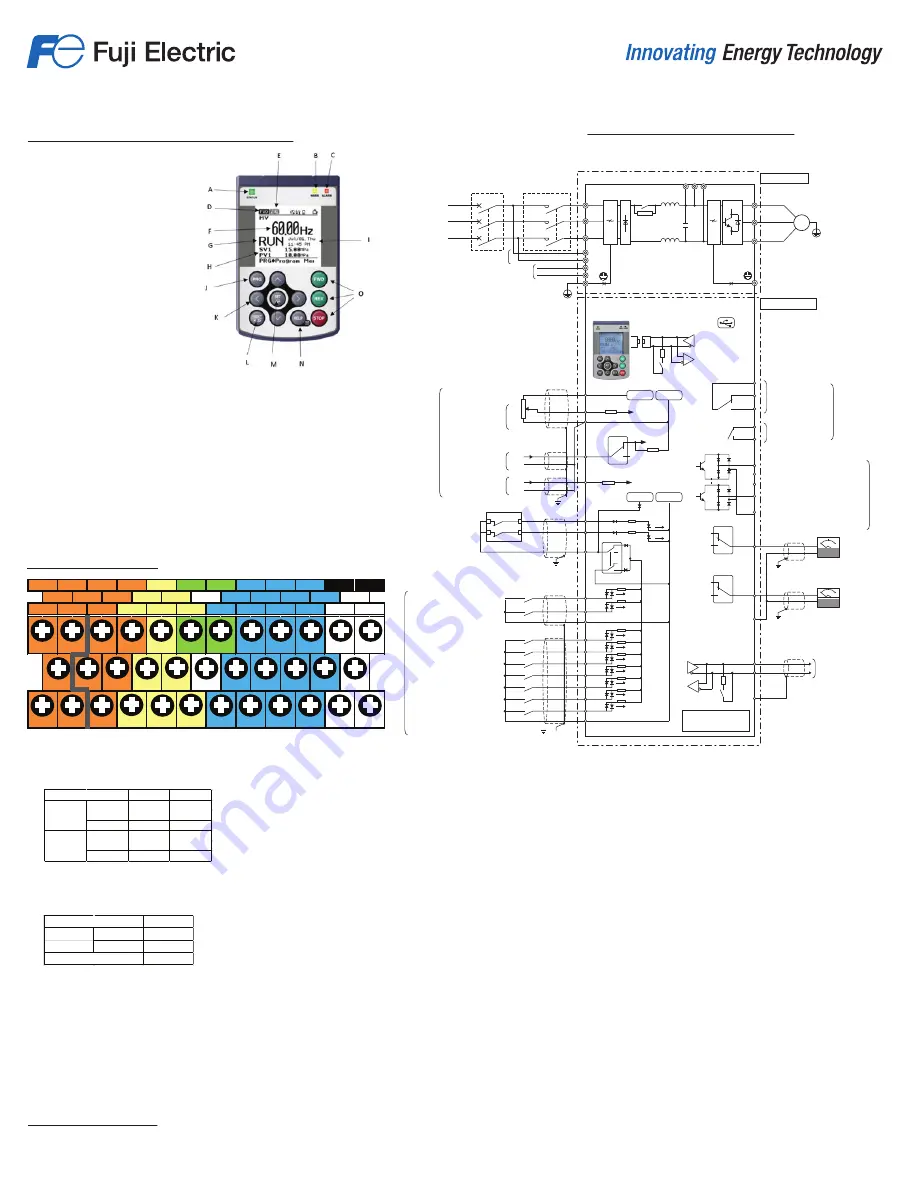
Control Card Terminals
FRENIC-HVAC Control Wiring
*1) To retain an alarm output signal ALM issued on inverter's programmable output terminals by the protective
function or to keep the keypad alive even if the main power has shut down,
connect these terminals to the power supply lines. Even without power supply to these terminals, the inverter
can run.
*2) Terminals [Y1] to [Y4] (transistor outputs) support both SINK and SOURCE modes.
*3) When the Enable function is not to be used, short-circuit terminals [EN1] and [PLC] and terminals [EN2] and
[PLC] using jumper wires. For opening and closing the hardware circuit between terminals [EN1] and [PLC] and
between [EN2] and [PLC], use safety components such as safety relays and safety switches. Be sure to use
shielded wires exclusive to terminals [EN1] and [PLC] and terminals [EN2] and [PLC]. (Do not put them together
with any other control signal wire in the same shielded core.)
*4) Usually there is no need to do anything regarding the EMC filter.
When the leakage current due to the built-in EMC filter causes problems with the power supply system,
removing screws from terminals [E1] and [E2] may improve the problem.
Note that doing so the effect of the EMC filter is lost, and therefore the inverter is no longer compliant with the
EMC standards. To remove those screws, consult your Fuji Electric representative.
*5) Normally there is no need to connect it. Must be connected if inverter is supplied from regenerative PWM
converter (RHC Series) or from DC power supply.
EN2
Y5A
Y5C
Y3
Y4
V2
FM1
FM2
X5
X6
X7
X1
X2
X3
X4
EN1
30B
Y1
Y2
C1
11
30A
30C
CMY
11
12
DX -
13
CM
FWD
REV
PLC
SD
CM
DX +
• FWD, Rev, plus 7 Digital inputs.
Configurable for Source or Sink.
• 2 0-10VDC analog inputs.
• 4-20mA analog input.
• 4 Transistor outputs.
• 2 0-10V or 4-20mA analog outputs.
• Form A contact relay
o (250VAC 0.3A, cosØ=0.3), (48VDC, .5A).
• Form C contact relay
o (250VAC 0.3A, cosØ=0.3), (48VDC, .5A).
• 24VDC max 200mA DC output power.
• 10VDC output power for potentiometer.
• 2 Source only, safe torque off Enable Inputs.
• RS-485 wiring connections.
Other Control Terminal
• RJ-45 keypad connection port.
• USB Type B connection port when using USB keypad (TP-E1U).
• 3 Option card expansion ports.
Min.
Max.
Opera
ti
ng
Voltage
(Sink)
O
ff
level
22V
27V
Opera
ti
ng
Voltage
(Sink)
O
ff
level
0V
2V
Item
ON level
0V
2V
ON level
22V
27V
Max.
Opera
ti
ng
ON level
2V
Voltage
O
ff
level
27V
50m A
Item
Maximum Current at on.
A. Run status indicator.
B. Overload Warning Indicator.
C. Alarm indicator.
D. Running direction.
E. Local Remote status monitor.
F. Main programmable Operation Monitor display.
G. Run/Stop Fault Status.
H. 2 additional programmable Operation Monitor displays.
I. Date and Time display.
J. Program button.
K. Menu navigation arrow keys.
L. Alarm reset and previous screen key.
M. Set key for storing changes.
N. Remote and Local toggle and help button.
O. Local mode control operators.
FRENIC-HVAC Multi-Function Keypad
M
Alarm relay output
(for any fault)
AX terminal
function
Data send/receive
RS-485
communications
port 2 (terminal
block)
Analog
RS-485 communications port 1
(RJ-45 connector for
keypad connection)
During operation
Frequency (speed) agreement
Frequency (speed) detection
Motor overload early warning
Common terminal
(Shared between sink and source)
frequency meter
Analog
frequency meter
0V
+24VDC
0V
+10VDC
Setting voltage input
0~±10VDC
Setting voltage input
(0~+10VDC)
(0~±10VDC)
0~10VDC
3~
Setting current input
4~20mADC
(0~20mADC)
4~20mADC
(0~20mADC)
0~10VDC
4~20mADC
(0~20mADC)
Control power AUX input *1
Fan power supply auxiliary input *5
Power supply
400V series
380V~480V
50/60Hz
Ground terminal
Main circuit
Ground terminal
Potentiometer
power supply
Magnetic contactor
(MC)
L1/R
L2/S
L3/T
13
12
11
1
3
2
R0
T0
R1
T1
G
E1
G
U
V
W
Enable input 1
Enable input 2
REV
CM
CM
X1
X2
X3
X4
X5
X6
X7
FWD
EN1
PTC
FWD operation/stop command
REV operation/stop command
Digital input common
Multi-step frequency selection (0~1steps)
Multi-step frequency selection (0~3steps)
Self-hold selection
Coast-to-stop command
Alarm reset
Frequency setting 2/frequency setting 1
Local (keypad) instruction selection
Digital input common
FM1
CMY
Y2
Y1
30C
30B
30A
Y5C
Y5A
30
Y3
Y4
FM2
11
SD
V2
C1
C1
SW5
EN2
PLC
SW1
SOURCE
SINK
SW4
SW6
SW3
SW2
*
7
MCCB
or ELCB
(+)
(-)
(+)
(-)
DX+
DX-
USB port
Motor
P(-)
P(+)
N(-)
Analog input
Digital input
Contact point output
Control circuit
Transistor
output
*
4
*4
E2
*
3
*
2


