


AAØZZ EZKeyer III 23 November 2014
- 1 -
Copyright 2014 AAØZZ
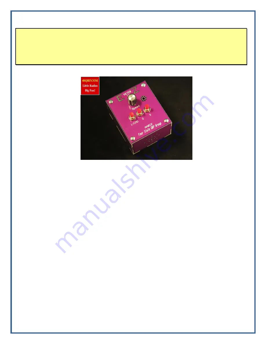
EZKeyer III
By Craig Johnson, AAØZZ
A Complete, Easy-to-Use, Standalone CW Keyer
TABLE OF CONTENTS
1
Introduction .............................................................................................................................................. 1
2
Features ..................................................................................................................................................... 2
3
Components .............................................................................................................................................. 2
4
Building the PC Board .............................................................................................................................. 3
5
Building the Case ..................................................................................................................................... 8
6
Installing the PC Board in the Case ........................................................................................................ 13
7
Using the EZKeyer III ............................................................................................................................ 15
7.1
Powering the EZKeyer III .............................................................................................................. 15
7.2
Installing a larger speaker ............................................................................................................... 15
7.3
Installing a Knob on the Speed Pot ................................................................................................ 16
7.4
Quick test before using ................................................................................................................... 16
7.5
Getting familiar with the EZKeyer III ............................................................................................ 16
8
EZKeyer III Commands ......................................................................................................................... 18
Appendix A – Mute Timing Diagram ............................................................................................................ 20
Appendix B – EZKeyer III PC Board Schematic ........................................................................................... 22
Appendix C – EZKeyer III PC Board Parts Placement .................................................................................. 23
Appendix D – EZKeyer III Parts List ............................................................................................................. 24
1 Introduction
This full featured PIC-based iambic Morse code keyer features three memories and is very easy use. It
has many of the features of the high end keyers while maintaining ease of use. Commands are entered


