

Esc
Enter
CONSOLE
I N T E R N A L
E X T E R N A L
D M Z
HA
1
2
3
4
USB
800F
P W R
Connector Type
Speed
Protocol Description
Internal
LC SFP 1000Base-SX
Ethernet
Connection to the internal network.
External
LC SFP 1000Base-SX
Ethernet
Connection to the Internet.
DMZ
LC SFP 1000Base-SX
Ethernet
Optional connection to a DMZ network.
HA
LC SFP 1000Base-SX
Ethernet
Optional connection to other FortiGate-800F units for
high availability (HA).
1 to 4
RJ-45
10/100 Base-T
Ethernet
Optional connections to other networks.
CONSOLE
RJ-45
9,600 bps
RS-232
Optional connection to the management computer.
Provides access to the command line interface (CLI).
FortiGate-800F LED indicators
Factory defaults
LED
State
Description
Power
Green
The FortiGate-800F unit is powered on.
Off
The FortiGate-800F unit is powered off.
Internal
External
DMZ
HA
Amber
The correct cable is in use and the connected equipment has
power.
Flashing
Amber
Network activity at this interface.
Off
No link established.
Interface
Internal
External
DMZ
192.168.1.99
192.168.100.99
10.10.10.1
HA
0.0.0.0
NAT/Route mode IP addresses
IP
Transparent mode IP address
admin
(none)
Administrator account settings
User Name
Password
MANAGEMENT IP 10.10.10.1
Interface
IP
1 to 4
0.0.0.0
Connect the FortiGate-800F unit to a power outlet and to the internal and external networks.
NAT/Route mode
In NAT/Route mode, each FortiGate-800F unit is visible to the networks that it is
connected to. All of its interfaces are on different subnets. Each interface that is
connected to a network must be configured with an IP address that is valid for that
network.
You would typically use NAT/Route mode when the FortiGate-800F unit is deployed as
a gateway between private and public networks. In its default NAT/Route mode
configuration, the unit functions as a firewall. Firewall policies control communications
through the FortiGate-800 unit. No traffic can pass through the FortiGate-800 unit until
you add firewall policies.
In NAT/Route mode, firewall policies can operate in NAT mode or in Route mode. In
NAT mode, the FortiGate-800F unit performs network address translation before IP
packets are sent to the destination network. In Route mode, no translation takes place.
Transparent mode
In Transparent mode, the FortiGate-800F unit is invisible to the network. All of its
interfaces are on the same subnet. You only have to configure a management IP
address so that you can make configuration changes.
You would typically use the FortiGate-800F unit in Transparent mode on a private
network behind an existing firewall or behind a router. In its default Transparent mode
configuration, the unit functions as a firewall. No traffic can pass through the
FortiGate-800F unit until you add firewall policies.
You can connect up to 8 network segments to the FortiGate-800F unit to control traffic
between these network segments.
FortiGate-800F Unit
in NAT/Route mode
Route mode policies
controlling traffic between
internal networks.
Internal network
DMZ network
Internal
192.168.1.99
DMZ
10.10.10.1
192.168.1.3
10.10.10.2
External
204.23.1.5
NAT mode policies controlling
traffic between internal and
external networks.
Internet
Esc
Enter
CONSOLE
1
2
3
4
USB
800F
I N T E R N A L
E X T E R N A L
D M Z
HA
P W R
Internal network
10.10.10.3
FortiGate-800F Unit
in Transparent mode
10.10.10.1
Management IP
External
Internal
10.10.10.2
Transparent mode policies
controlling traffic between
internal and external networks
204.23.1.5
(firewall, router)
Gateway to
public network
Internet
Esc
Enter
CONSOLE
1
2
3
4
USB
8
I N T E R N A L
E X T E R N A L
D M Z
HA
P W R
Before beginning to configure the FortiGate-800F, you need to plan how to integrate the unit into
your network. Your configuration plan is dependent upon the operating mode that you select:
NAT/Route mode (the default) or Transparent mode.
Web-based
manager and
Setup Wizard
The FortiGate web-based
manager is an easy to use
management tool.
Use it to configure the
administrator password, the internal, external and DMZ
interface addresses, the default gateway address, and
the DNS server addresses.
Requirements:
•
The Ethernet connection between the FortiGate-
800F and management computer.
•
Internet Explorer version 6.0 or higher on the
management computer.
Command Line
Interface (CLI)
The CLI is a full-featured
management tool.
Use it to configure the
administrator password,
the interface addresses,
the default gateway
address, and the DNS
server addresses. To
configure advanced settings, see the Documentation
CD-ROM.
Requirements:
•
The RJ-45-serial connection between the
FortiGate-800F and management computer.
•
A terminal emulation application (HyperTerminal for
Windows) on the management computer.
Control
Buttons &
LCD
The control buttons and LCD are located on the front
panel of the FortiGate-800F. Use them to configure the
internal, external and DMZ interface addresses, and the
default gateway address. To configure the other
interface addresses, and the DNS server addresses,
use the web-based manager or the CLI.
Requirements:
•
Physical access to the FortiGate-800F.
Choose among three different tools to configure the FortiGate-800F.
QuickStart Guide
FortiGate-800F
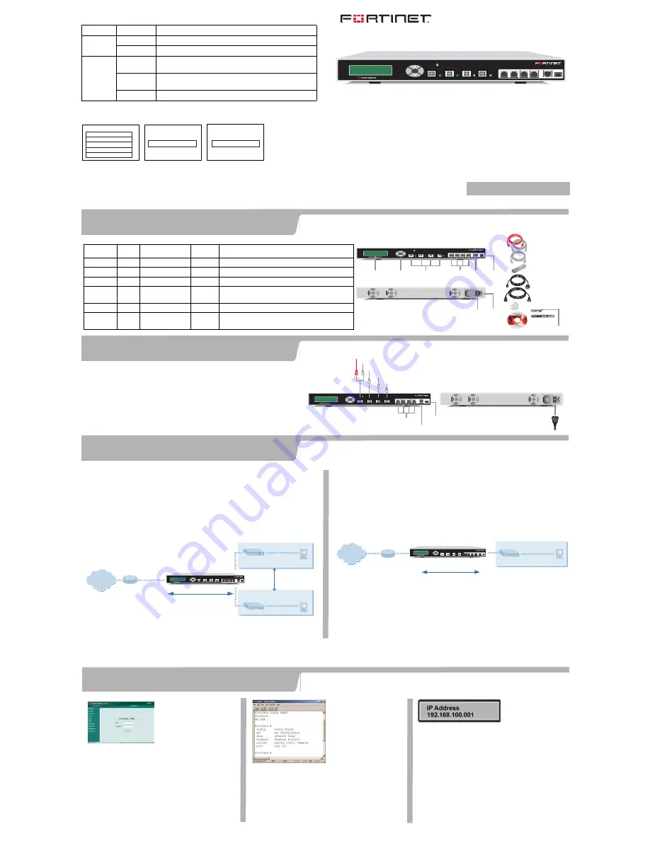
Check that the package contents are complete.
Esc
Enter
CONSOLE
1
2
3
4
USB
8
Front
1 to 4
Interface
LCD
Control
Buttons
Fiber-optic Internal,External,
DMZ HA Interface
Power
Connection
Serial
Port
Power
Switch
USB
(future)
Back
Power Cable
Rack-Mount Brackets
RJ-45 Serial Cable
Ethernet Cables:
Orange - Crossover
Grey - Straight-through
Documentation
USER MANUAL
FortiGate-800
QuickStart Guide
Copyright 2003 Fortinet Incorporated. All rights reserved.
Trademarks
Products mentioned in this document are trademarks.
Esc
Enter
CONSOLE
I N T E R N A L
E X T E R N A L
D M Z
HA
1
2
3
4
USB
8
P W R
I N T E R N A L
E X T E R N A L
D M Z
HA
P W R
RJ-45 to
DB-9 Serial Cable
x4 SFP Transceivers
•
Place the unit on a stable surface or mount it in a 19-inch rack. It requires
1.5 inches (3.75 cm) clearance on each side to allow for cooling.
•
Make sure the power switch on the back of the unit is turned off before
connecting the power and network cables.
•
MAIN MENU appears when the unit is up and running.
Esc
Enter
CONSOLE
1
2
3
4
USB
800F
Power cable connects to power outlet
Fiber-optic Ethernet connects to Internet (public switch, router or modem)
Fiber-optic Ethernet cable connects to DMZ network
Fiber-optic Ethernet cable connects to another FortiGate-800 for HA
Straight-through Ethernet cables connect to other networks
Optional RJ-45 serial cable connects to management computer
USB (future use)
Straight-through Ethernet cable connects to LAN or switch on internal network
Crossover Ethernet cable connects to management computer on internal network
or
I N T E R N A L
E X T E R N A L
D M Z
HA
P W R
Checking the package contents
Checking the package contents
1
Connecting the FortiGate-800F
2
Planning the configuration
3
Choosing a configuration tool
4
© Copyright 2005 Fortinet Incorporated. All rights reserved.
Trademarks
Products mentioned in this document are trademarks or registered trademarks of their respective holders.
Regulatory Compliance
FCC Class A Part 15 CSA/CUS
12 January 2005
For technical support please visit http://www.fortinet.com.
Refer to the Documentation CD-ROM for information on how to control traffic, and how to configure HA, antivirus protection, Web content filtering, Spam filtering, intrusion
prevention (IPS), and virtual private networking (VPN).
01-28005-0061-20050112


