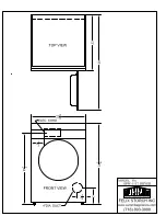
background image

Installation instructions

DGGX1US

Gas Dryer

Summary of Contents for Smartload DGGX1

Page 1: ...Installation instructions DGGX1US Gas Dryer ...

Page 2: ...ed according to the manufacturers instructions For your safety the information in this manual must be followed to minimize the risk of death personal injury fire explosion or property damage Do not store or use gasoline or other flammable vapors and liquids near this or any other appliance What to do if you smell gas Do not try to light or start any appliance Do not touch any electrical switch do ...

Page 3: ...moved from service or discarded remove the lid and drum door to the drying compartment 9 Do not reach into the appliance if the drum is moving 10 Do not install or store this appliance where it is exposed to water and or the weather 11 Do not tamper with the controls or the lid lock 12 Do not repair or replace any part of the appliance or attempt any servicing unless specifically recommended in th...

Page 4: ...s required 1 4 nut driver or socket wrench Phillips screwdriver Flat blade screwdriver Adjustable wrench that opens to 1 or 1 hex head socket wrench for adjusting the feet Adjustable wrench 8 or 10 20cm or 25cm for gas connections Level Pipe joint compound pipe dope or tape for gas pipe connections that is resistant to LP Propane Butane and Natural Gas Caulking gun and compound for installing new ...

Page 5: ...ure that the electrical and gas installation meets all national and local codes and ordinances Location requirements WARNING Explosion Hazard Keep flammable materials and vapours such as gasoline away from the dryer Place dryer at least 18 inches 46 cm above the floor for a garage installation Failure to do so can result in death explosion fire or burns The dryer must be installed or stored in an ...

Page 6: ... dryer in a closet alcove it must be exhausted to the outdoors No other fuel burning appliance can be installed in the same closet or alcove The top opening area in the door must be a minimum of 48 square inches 310cm2 and the bottom opening area must have a minimum of 24 square inches 155cm2 These openings must never be obstructed a louvred door with the minimum air opening is acceptable Minimum ...

Page 7: ...Dimensions Lid clearance Check that there is enough clearance for the lid to fully open Exhaust outlet location 13 7 8 352mm 13 1 8 333mm Exhaust outlet 4 3 8 111mm 7 ...

Page 8: ...choring the dryer to the floor must be made A Mobile Home Installation kit is available with instructions see Accessories page 4 Locate in an area that has adequate make up air a minimum of 72 square inches of unobstructed opening is required Mobile home installations must be exhausted to the outdoors with the exhaust duct termination securely fastened to the mobile home structure using materials ...

Page 9: ...ght rigid metal ducting will minimise lint accumulation Thick wall flexible metal ducting may be used but care must be exercised to avoid sharp bends which may squash the duct cause blockages Do not use plastic ducting or thin wall flexible metal ducting Use duct tape to secure joints Do not use screws as they collect lint Keep ducting as short and straight as possible Do not exceed the maximum ex...

Page 10: ...ient movement Static pressure in the exhaust ducting does not exceed 1 inch 250Pa or is not less than 0 inches of water column ie negative pressure when measured with a manometer in the first 6 inches of the duct with the dryer running on Air Dry no heat setting The exhaust duct system meets all relevant local state and national codes All ducting should be inspected and cleaned at least once a yea...

Page 11: ...he number of elbows or bends used 1 Refer to the exhaust duct length chart that matches your hood type for the maximum duct lengths you can use Do not use duct runs longer than specified in the exhaust duct length charts refer to next page Exhaust duct systems longer than specified will Accumulate lint creating a potential fire hazard Shorten the life of the dryer Reduce performance resulting in l...

Page 12: ... Acceptable 2 1 2 Hood When you have a 2 1 2 6cm Hood Maximum length of 4 diameter metal duct Number of 90 elbows bends Rigid Thick Wall Flexible Metal fully extended 0 58ft 17 6m 28ft 8 5m 1 48ft 14 6m 23ft 7 0m 2 38ft 11 5m 19ft 5 7m 3 29ft 8 8m 17ft 5 1m 4 21ft 6 4m 15ft 4 5m For exhaust systems not covered by the exhaust duct length charts such as multiple unit hook ups plenums and power assis...

Page 13: ...collar sections separate fittings can face same or opposite beveled edges allow corner installations swivel collar wall connection telescoping sections Extra long band clamp for dryer connection The maximum length using a 2 x 6 5cm x 15cm rectangular duct with two elbows and a 2 1 2 6 3cm exhaust hood is 8ft 2 4m Refer to the venting system kit manufacturers instructions 13 ...

Page 14: ... sheet metal screws when assembling ducting Always use suitable duct tape Never use plastic or thin metal foil flexible exhaust material 2 The exhaust outlet is located close to the center of the rear of the dryer Make sure you join the exhaust duct to the dryer with duct tape only This will prevent lint and dust from escaping from the dryer and exhaust system 13 7 8 352mm 13 1 8 333mm Exhaust out...

Page 15: ...re dryer is in a suitable location for installation Consider installing the dryer before the washing machine in a side by side installation this will allow better access to electrical and exhaust connections Remove packaging 2 1 4 3 6 5 Tilt Walk off Slide out 1 Remove straps 4 Remove the carton by lifting it off the product do not cut the carton off 5 Remove the basepacker by tilting the product ...

Page 16: ...ryer back using a hand trolley and making sure the trolley and dryer are secure 2 Fit a rubber insert to each plastic foot as shown 3 Screw the feet into the foot retainers on the left hand and right hand sides as shown 4 Screw both feet in so they protrude 1 2 12mm below the bottom of the wall on the foot retainers 16 ...

Page 17: ...oviding a path of least resistance for electric current This dryer is manufactured with a cabinet grounding conductor and plug The plug must be plugged into the correct type of outlet which has been properly installed and grounded in accordance with local codes and ordinances WARNING Electrical Shock Hazard Check with a qualified electrician or serviceman if you are in doubt as to whether the appl...

Page 18: ...ted on the back splash If this information does not agree with the type of gas available in your home contact your local Fisher Paykel supplier or service center Natural Gas This dryer is supplied ready for use with Natural Gas It is design certified by UL International for LP Propane or Butane Gases with the appropriate conversion LP Gas conversion If the dryer is to be operated on LP Liquid Prop...

Page 19: ... this elevation The dryer must be isolated from the gas supply piping system by closing the supply shut off valve during any pressure testing of the gas supply piping system Gas ignition This dryer has an automatic ignition system to ignite the burner There is no pilot flame burning in this dryer Connecting to the gas supply 1 The gas supply line should be 1 2 inch 2 A shut off valve must be insta...

Page 20: ...the kit 6 Copper tubing should not be used for Natural Gas and if used for LP Gas it must be LP Gas compatible 7 Disconnect and discard old flexible tubing 8 The gas pipe that comes out of the rear of your dryer has on it a NPT male thread Remove the protective cap and apply sealing compound or tape to the thread Thread sealant should be appropriate for the type of gas to be used 3 8 NPT pipe thre...

Page 21: ...operly grounded Gas is turned on before attempting to start the dryer All fittings in the gas line are tested for leaks Dryer starts heats cools and shuts off Exhaust temperature increases to confirm ignition has occurred If ignition does not occur initially it may be due to air in the gas line or low voltage power supply The gas regulator valve may fail to open if the power supply falls below 105...

Page 22: ...22 ...

Page 23: ...23 ...

Page 24: ... at the date of issue Under our policy of continuous product improvement these specifications may change at any time You should therefore check with your Customer Care Center to ensure this booklet correctly describes the product currently available www fisherpaykel com US Installation Instructions Published 03 2004 Part No 395520A ...

Reviews: