background image

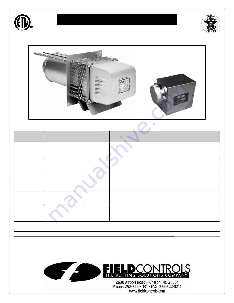
SIDEWALL POWER VENTER KIT  

Model: 

SWGII-5,6 AGA and SWG-8*


FOR COMMERCIAL WATER HEATERS 

*Patented


TYPICAL VENTING SYSTEM COMPONENTS: 

PART 

NUMBER 

DESCRIPTION 

APPLICATION 

239-81764-00 

SWGII-5 POWER VENTER, 

CK-41 24 VOLT CONTROL KIT 

COMMERCIAL WATER HEATERS WITH 24 VOLT 

CONTROLS WITH INPUT RATINGS OF UP TO 290,000 

BTU/HR. 

239-81765-00 

SWGII-5 POWER VENTER, 

CK-81 MILLIVOLT CONTROL KIT 

COMMERCIAL WATER HEATERS WITH MILLIVOLT 

CONTROLS WITH INPUT RATINGS OF UP TO 290,000 

BTU/HR. 

239-81766-00 

SWGII-6 POWER VENTER, 

CK-41 24 VOLT CONTROL KIT 

COMMERCIAL WATER HEATERS WITH 24 VOLT 

CONTROLS WITH INPUT RATINGS GREATER THAN 

290,000 BTU/HR. UP TO 416,000 BTU/HR. 

239-81767-00 

SWGII-6 POWER VENTER, 

CK-81 MILLIVOLT CONTROL KIT 

COMMERCIAL WATER HEATERS WITH 24 VOLT 

CONTROLS WITH INPUT RATINGS GREATER THAN 

290,000 BTU/HR. UP TO 416,000 BTU/HR. 

239-82148-00 

SWG-8 POWER VENTER, 

CK-41 24 VOLT CONTROL KIT 

COMMERCIAL WATER HEATERS WITH 24 VOLT 

CONTROLS WITH INPUT RATINGS GREATER THAN 

415,000 BTU/HR. 


DO NOT DESTROY 

THESE INSTRUCTIONS MUST REMAIN WITH EQUIPMENT 


Summary of Contents for 46256400

Page 1: ... CONTROLS WITH INPUT RATINGS OF UP TO 290 000 BTU HR 239 81766 00 SWGII 6 POWER VENTER CK 41 24 VOLT CONTROL KIT COMMERCIAL WATER HEATERS WITH 24 VOLT CONTROLS WITH INPUT RATINGS GREATER THAN 290 000 BTU HR UP TO 416 000 BTU HR 239 81767 00 SWGII 6 POWER VENTER CK 81 MILLIVOLT CONTROL KIT COMMERCIAL WATER HEATERS WITH 24 VOLT CONTROLS WITH INPUT RATINGS GREATER THAN 290 000 BTU HR UP TO 416 000 BT...

Page 2: ... flue damper closes POWER VENTER KIT FOR MILLIVOLT CONTROLS CK 81 CONTROL KIT 1 When the aquastat contacts close the 24 volt circuit is completed from the transformer through the wiring harness and switch contacts and through the relay coil causing the motor relay contacts to close and start the power venter blower 2 When the blower reaches operating speed the vacuum near the blower causes the pre...

Page 3: ...re conditions To ensure extreme negative pressure does not exist follow General Installation Inspection of this manual 7 The commercial water heaters for the SWGII 5 and 6 power venters have draft hoods and each kit includes a GSK 3 spillage switch which must be installed on the bottom of the draft hood to detect spillage of flue products due to inadequate venting draft or vent system blockage In ...

Page 4: ...tem in accordance with manufacturer s instructions will result in conditions which may produce bodily injury and or property damage 1 Remove power venter from box and inspect unit for damage If the carton has been crushed or mutilated check unit very carefully for damage Rotate blower wheel to insure that the motor and blower wheel rotate freely DO NOT install if any damage is apparent Refer to un...

Page 5: ...rial and the flue gas temperature is above 400EF at the power venter inlet line the square hole with a piece of corrosion resistant sheet metal or non combustible material The liner piece should be the same width as the wall section See Figure 3 The power venter has maximum flue gas temperature of 550EF at the power venter inlet Figure 7 shows how the airflow pattern through an SWG reduces the req...

Page 6: ...ING SINGLE WALL VENT PIPE INSTALLATION CLEARANCE WITH SINGLE WALL VENT PIPE DOUBLE PIPE SYSTEM SINGLE PIPE SYSTEM ALLOWABLE INLET TEPERATURE CLEARANCE A ALLOWABLE INLET TEMPERATURE CLEARANCE B 400 F OR LESS INCH MINIMUM 400 F OR LESS 3 INCH MINIMUM 400 F TO 550 F 1 INCH MINIMUM 400 F TO 550 F 4 INCH MINIMUM 400 F TO 550 F INCH MINIMUM WITH SHEET METAL LINER 400 F TO 550 F 3 INCH MINIMUM WITH SHEET...

Page 7: ...CAUTION MUST be taken to ensure that the wiring does not come in contact with any heat source All line voltage and safety control circuits between the power venter and the appliance MUST be wired in accordance with the National Electrical Code for Class 1 wiring or equivalent CK 41 CONTROL KIT WIRING FOR 24 VOLT WATER HEATER CONTROLS 1 Remove the wiring harness supplied with the control kit 2 Remo...

Page 8: ...he joists at regular intervals to prevent sagging 10 Run the low voltage wires into the control box through hole with plastic bushing and connect the wires as follows Connect the black wire to terminal T1 the red wire to T2 and the yellow wire to T3 See Figures 11 and 12 11 Follow the National Electrical Code and or applicable local codes for running high voltage wires to the CK 41 control box an ...

Page 9: ...Figure 11 Page 9 ...

Page 10: ...Figure 12 Page 10 ...

Page 11: ...pping sheet metal screw supplied The thermal element disc should hang just below the draft hood relief opening See Figure 10 7 Run the two 2 red wires from the break in the top of the harness into the spillage switch through the plastic bushing opening and connect to the switch terminals 8 Run the harness to the CK 81 junction box which will be mounted in a convenient location near the power vente...

Page 12: ...ded as a guide to aid in determining that the venting system is properly installed and is in a safe condition for continuous use This procedure should be recognized as a generalized procedure which cannot anticipate all situations Accordingly in some cases deviation from this procedure may be necessary to determine safe operation of the equipment If it is determined that a condition exists which c...

Page 13: ...ar any soot ash or coating which inhibits either rotation or air flow Remove all foreign materials before operating 3 Vent System Inspect all vent connections annually for looseness for evidence of corrosion and for flue gas leakage Replace seal or tighten pipe connections if necessary 4 System Safety Devices With the heating system operating disconnect the pressure sensing tube from the pressure ...

Page 14: ...ssembly See Figure 17 2 Slide the motor assembly onto the protruding threaded studs on the venter body with the exhaust chute pointing downward and replace the four nuts securely to the threaded studs 3 Reattach the flexible conduit and wires to the motor and secure the cover on the electrical box 4 Install the motor cover with the side louvers pointing downward INITIAL BURNER AND VENTING SYSTEM O...

Page 15: ...__ INSTALLER S NAME _____________________________________________________ INSTALLER S COMPANY __________________________________________________ INSTALLER S PHONE NO _________________________________________________ DATE OF INSTALLATION _________________________________________________ Page 15 ...

Page 16: ...PN 46256400 Rev B 7 00 ...

Reviews: