Fibocom L610-LA, Hardware Manual
The Fibocom L610-LA is a cutting-edge IoT module designed for seamless connectivity. For detailed instructions on installation and usage, download the free Hardware Manual from our website. Explore the features and functionalities of the device to maximize its potential. Get your manual at manualshive.com.
Share
Download


Reviews:
No comments
Related manuals for L610-LA

ET-UW100
Brand: Abocom Pages: 14

AP12I360
Brand: Everest Pages: 26

Oolite V3.5
Brand: Gainstrong Pages: 14

L1-RW332
Brand: Link-One Pages: 77

Rocket5AC R5AC-PTP
Brand: Ubiquiti Pages: 13

AC1750
Brand: Linksys Pages: 124
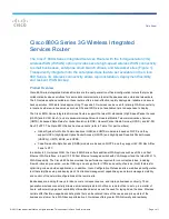
880G Series
Brand: Cisco Pages: 9

USC 3330
Brand: Cisco Pages: 12

Small Business WAP551
Brand: Cisco Pages: 4

Linksys WRT120N
Brand: Cisco Pages: 35

WUMC710
Brand: Cisco Pages: 17

VEN501
Brand: Cisco Pages: 2

Linksys WRT54GS2
Brand: Cisco Pages: 6

Linksys E2100
Brand: Cisco Pages: 10

Linksys SE1500
Brand: Cisco Pages: 2

Linksys WRT54G3G
Brand: Cisco Pages: 3

Linksys WRT320N
Brand: Cisco Pages: 54

Linksys X-Series
Brand: Cisco Pages: 27


