ferroamp ESS Power Case, Installation Manual
The ferroamp ESS Power Case Installation Manual is a comprehensive guide that provides step-by-step instructions for setting up and utilizing this innovative energy storage solution. This manual is available for free download at manualshive.com, enabling users to easily access the necessary information to optimize their ferroamp ESS Power Case experience.
Share
Download


Reviews:
No comments
Related manuals for ESS Power Case

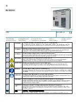
SLIM
Brand: Siemens Pages: 4

XJ-L Busway System
Brand: Siemens Pages: 6

SIVACON 8PS LR Series
Brand: Siemens Pages: 8

SIVACON 8PS BD2C EESC Series
Brand: Siemens Pages: 6

SIVACON 8PS LD Series
Brand: Siemens Pages: 8
SIVACON S 8PQ Series
Brand: Siemens Pages: 40

WL Series
Brand: Siemens Pages: 362

FlexPDU
Brand: Eaton Pages: 24

ePDU
Brand: Eaton Pages: 27

EVOline Port 1129
Brand: Schulte Elektrotechnik Pages: 2

ASR-2000 Series
Brand: GW Instek Pages: 224

SMISSLINE TP
Brand: ABB Pages: 2

PC Standby Stop
Brand: SAVEPOWER Pages: 2

Dominion Px
Brand: Raritan Pages: 281

DPBF1U Series
Brand: Unipower Pages: 16

RELION 650 SERIES
Brand: ABB Pages: 68

Portable Power Distribution Box
Brand: Mennekes Pages: 24

Battery Protect BP 200
Brand: Victron energy Pages: 21


