Feider FAST175P, User Manual
The Feider FAST175P is a powerful and reliable product designed to ease your gardening tasks. To ensure you make the most of its features, don't forget to grab your free User Manual. Download it from our website manualshive.com for a step-by-step guide, enabling you to operate the FAST175P effortlessly.
Share
Download


Reviews:
No comments
Related manuals for FAST175P
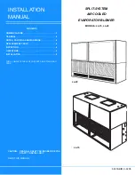
LL-15
Brand: Unitary products group Pages: 20

HLS 215
Brand: Hurricane Pages: 60

Thermo-bug AirBlower
Brand: Fleschhut Pages: 5

380
Brand: MTD Pages: 16

3276000660200
Brand: STERWINS Pages: 217

E600E
Brand: MTD Pages: 28

Two-Stage Snow Thrower 300series
Brand: MTD Pages: 36

4344
Brand: Verdemax Pages: 20

DVFFBK
Brand: Desa Pages: 1

G3G180-AD43-71
Brand: ebm-papst Pages: 11

AA245
Brand: FMG Pages: 20

1500 Series
Brand: Cool Machines Pages: 49

51619
Brand: Toro Pages: 8

E602E
Brand: Yard Machines Pages: 28

769-03412
Brand: Yard-Man Pages: 44

GCB-260
Brand: Gardener's Choice Pages: 12

378378 2110
Brand: Parkside Pages: 148

ES-2100
Brand: Echo Pages: 58


