Fastwel CPC309, User Manual
The Fastwel CPC309 User Manual is available for download, free of charge, from our website. This comprehensive manual provides all the necessary information for effectively using the Fastwel CPC309 product. Gain valuable insights and maximize your experience with our succinct and easily accessible user manual.
Share
Download


Reviews:
No comments
Related manuals for CPC309

MTX Series
Brand: Yamaha Pages: 157

airTools 6200
Brand: Symetrix Pages: 33
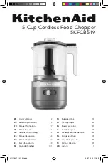
5KFCB519
Brand: KitchenAid Pages: 14

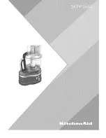
5KFP0933
Brand: KitchenAid Pages: 40
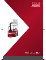
KFP1642
Brand: KitchenAid Pages: 32
5KFP13CR
Brand: KitchenAid Pages: 4

KFP1133
Brand: KitchenAid Pages: 68

5KFC3516EOB
Brand: KitchenAid Pages: 260
5KFP1644ACA0
Brand: KitchenAid Pages: 31

KFP740
Brand: KitchenAid Pages: 88

5KFP1335
Brand: KitchenAid Pages: 25

5KFP1333
Brand: KitchenAid Pages: 24

5KFP1333GER
Brand: KitchenAid Pages: 23

5KFC3516T
Brand: KitchenAid Pages: 24

5KFC3516P
Brand: KitchenAid Pages: 12

5KFP1664
Brand: KitchenAid Pages: 2

KFP715BW0
Brand: KitchenAid Pages: 4

5KFPCB700A
Brand: KitchenAid Pages: 21


