Fagor HTT 100, User Manual
The Fagor HTT 100 User Manual is a comprehensive guide that allows you to easily unlock the full potential of your Fagor HTT 100 device. With step-by-step instructions and clear illustrations, this manual provides quick troubleshooting tips and offers insightful tips to enhance your user experience. Download your free manual from manualshive.com today and master your Fagor HTT 100 hassle-free.
Share
Download


Reviews:
No comments
Related manuals for HTT 100

SC200
Brand: LEXIBOOK Pages: 15

PLC650
Brand: LEXIBOOK Pages: 33

KCA-R2FMA
Brand: Kenwood Pages: 36

KCA-R30FM
Brand: Kenwood Pages: 24
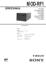
MOD-RF1
Brand: Sony Pages: 10
DSM-T1
Brand: Sony Pages: 16
DSM-T1
Brand: Sony Pages: 19

DSM-R1
Brand: Sony Pages: 19

MCP-800
Brand: IKUSI Pages: 4

FX-7400GII
Brand: Casio Pages: 412

Godfazer
Brand: D16 Group Pages: 52

3416
Brand: Calculated Industries Pages: 41

UFO compact 386/TP
Brand: Kathrein Pages: 64

watch any were WS-6990
Brand: GBS Elettronica Pages: 14

PAC-10
Brand: MACOM Pages: 54

FMT-B8
Brand: Tellur Pages: 10

5808730
Brand: Texas Instruments Pages: 102


