F.u.n.k.e. 800ATC-H-260-260, Operation And Installation
The F.u.n.k.e. 800ATC-H-260-260 is a cutting-edge industrial-grade device designed for efficient and reliable air traffic control operations. This user-friendly product ensures seamless installation and operation. For detailed instructions, download the free Operation and Installation manual from our website.
Share
Download


Reviews:
No comments
Related manuals for 800ATC-H-260-260

ZP9D-115RM-LR
Brand: B&B Electronics Pages: 55

Zlinx ZP Series
Brand: B&B Electronics Pages: 70

H5000 Pilot
Brand: B&G Pages: 3

JMS4
Brand: Jensen Pages: 14
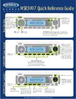
MSR3007
Brand: Jensen Pages: 2

GPSMAP 7400 Series
Brand: Garmin Pages: 8

Multimode 3
Brand: Ham International Pages: 25

ELARA LN05
Brand: TriangleTube Pages: 20

KBSOUND STAR
Brand: EisSound Pages: 21

WR-22
Brand: Sangean Pages: 41

TX3510
Brand: GME Pages: 36

hsb2 PLUS Series
Brand: Raymarine Pages: 2

HPG406D
Brand: Caliber Pages: 14

KK-E160
Brand: kchibo Pages: 4

FR-2115-B
Brand: Furuno Pages: 89

cNODE Maxi 31 Ex d
Brand: Kongsberg Pages: 50

190-01098-00
Brand: Garmin Pages: 62

ISM BAND XYR 5000 LINE
Brand: Honeywell Pages: 49


