


1
IMPO
RTAN
T:
Go to www
.extron.com f
or the complete
user guide
, installation instructions,
and
specifications bef
ore connecting the
product to the po
wer sour
ce.
HC 400 Series • Setup Guide
HC 404 and HC 403 Systems
The Extron HC 404 and HC 403 systems are AV presentation solutions. They incorporate a built-in control processor for display
control via HDMI Consumer Electronics Control (CEC), RS-232, IR, or Ethernet. They also include digital I/O ports.
Each system is a dedicated transmitter-receiver pair that is factory-optimized to work together as if it were a single unit.
Together each transmitter-receiver system extends video, audio, and control signals up to 230 feet (70 m) over a single CAT
x
cable.
An HC 404 TeamWork kit (which includes cables and other accessories) is also available.
Each system offers two auto-input switching modes, one of which automatically selects sources based on input signals and also
allows manual source selection via buttons. Auto-switching modes can be enabled or disabled via Extron Product Configuration
Software. The “last connected” auto-switching mode is enabled by default.
•
The
HC 404
features four AV inputs and one output. It consists of a three-input switching transmitter (HCT 103) and a scaling
receiver (HCR 102) that has one HDMI input and one connection from the transmitter. With the MBU 125 mounting brackets,
the transmitter can easily be mounted under a desk and the receiver can be mounted to a wall. Both the transmitter and
receiver feature half rack wide enclosures, and are also rack mountable.
•
The
HC 403
features three AV inputs and one output. It consists of a two-input switching transmitter (HCT 102 D) and
a scaling receiver (HCR 102) that has one HDMI input and one connection from the transmitter. The transmitter has a
decorator-style wallplate and can be mounted into a standard US 2-gang junction box; and the receiver is wall, furniture, or
rack mountable.
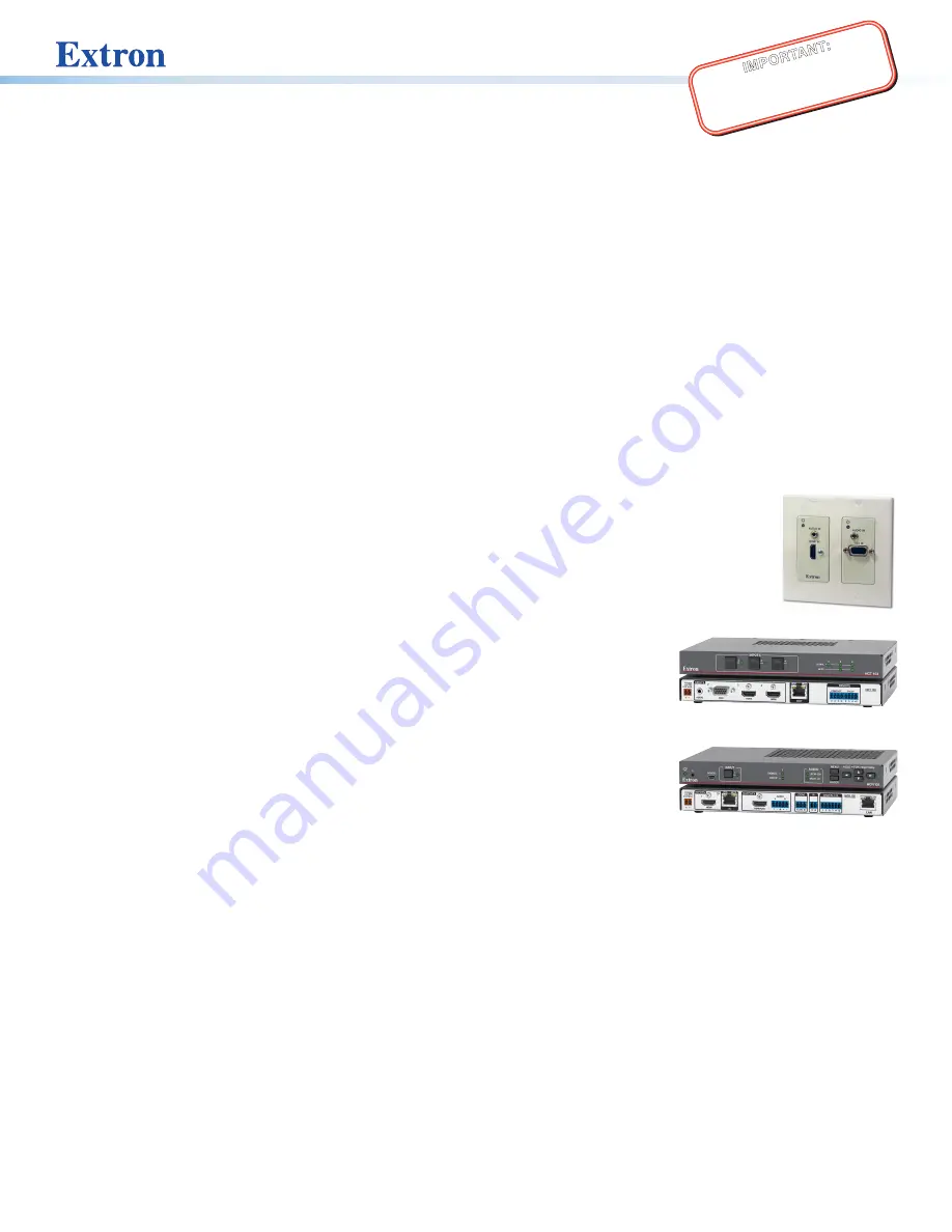
HCT 102 D
HCT 103
HCR 102
Transmitters
The HCT 102 D transmitter switches between an analog video and one digital (HDMI)
video input. It does not include input selection buttons and LEDs.
The HCT 103 transmitter switches between an analog video and two digital (HDMI) video
inputs. It includes front panel input selection buttons and LED signal indicators.
For either transmitter, if the selected input is HDMI, the extended video signal can be
HDCP-compliant.
Receiver
The HCR 102 receiver incorporates a high performance, HDCP compliant scaler that
scales video to provide a consistent output resolution to a display. It accepts video with
resolutions from 480i up to 1920x1200, 1080p, and 2K, and performs upscaling and
downscaling with multiple output rates up to 1920x1200, including HDTV 1080p/60 and
2K. The receiver includes an on-screen display, test patterns, and EDID Minder
®
.
This setup guide provides instructions for an experienced installer to install the HCT 103
or HCT 102 D and the HCR 102. The guide provides information needed to configure the most essential settings for the system
and the receiver. It also describes basic operations using front panel controls and the on-screen display (OSD) menu system. Full
details are available in the
HC 400 Series User Guide
.


