

X450-G2 Series Switch Quick Reference
For complete installation instructions see the
Extreme Networks
Summit Family Hardware Installation Guide
at:
www.extremenetworks.com/documentation
Hardware Components
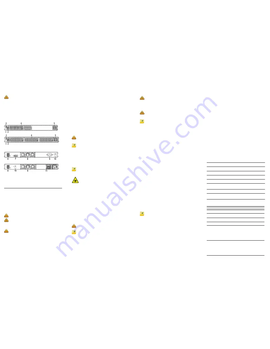
Figure 1
and
Figure 2
display the panel ports, LEDs, and hardware
components on the X450-G2 Series switches. See the
Extreme
Networks Summit Family Hardware Installation Guide
for component
details.
Figure 1
X450-G2 Switch Front Panels
Figure 2
X450-G2 Switch Back Panels
Installation Site Requirements
The installation site must be within reach of the network cabling and
meet the requirements listed below:
•
Appropriate grounded power receptacles must be located within 6
feet of the site.
•
A temperature of between 0°C (32°F) and 50°C (122°F) must be
maintained at the installation site with fluctuations of less than 10°C
(18°F) per hour.
•
Installing the system as described in this guide meets the protective
earth grounding requirements of the National Electrical Code (NEC)
UL 60950 and IEC 60950 standards. If it is necessary to use an
alternative grounding method, connect a 14 AWG wire between the
ground screw on the chassis and a nearby building ground point.
Handling the Switch
To prevent electrostatic damage, attach an electrostatic discharge
(ESD) wrist strap to your wrist before handling the switch.
Unpack the switch as follows:
1
Remove the packing material protecting the switch.
2 Remove the tape seal on the non-conductive bag to remove the
switch.
3 Perform a visual inspection of the switch for any signs of physical
damage. Contact Extreme Networks if there are any signs of
damage. See
“Getting Help”
for more information on contacting
Extreme Networks.
Electrical Hazard:
Only qualified personnel should perform
installation procedures.
Risques d'électrocution:
Seul un personnel qualifié doit effectuer
les procédures d'installation.
1
Stack LED
5
1000BASE-X SFP or
10G SFP+ ports
9
AC power input
connector
2
Console/Management
ports
6
21 Gb stacking port
(QSFP+)
10
Grounding screw
3
USB port
7
Redundant power
supply (RPS) connector
11
PoE+ power supply
bays
4
10/100/1000BASE-T or
10/100/1000BASE-T
PoE+ ports
8
Front-to-back fan
module slot
Caution:
To ensure proper ventilation and prevent overheating,
leave a minimum clearance space of 5.1 cm (2.0 in.) on both sides of
the device.
Warning:
A readily accessible disconnect device shall be
incorporated in the building installation wiring.
Avertissements:
Incorporez sur le circuit de câblage un dispositif de
déconnexion facilement accessible.
Caution:
The switch can be damaged by electrostatic discharge.
PoE+ Switch
Non-PoE Switch
Installing the Summit X450-G2 Series Switch
You can install a Summit X450-G2 Series switch in a rack. There are four
possible rack mounting configurations, depending upon whether:
•
The switch I/O ports or the power supply side of the device face
front
•
The device is mounted flush with the rack posts or mid-mounted
Stacking Switches
Up to eight X450-G2 Series switches can be stacked together and
connected, allowing the entire stack to operate with a single IP address.
You can use the following ports for stacking:
•
21Gb QSFP+ stacking ports
(
Figure 2
, callout 7)—For non-PoE
X450-G2 Series switches only. The stacking ports require QSFP+
direct attach passive copper cables, which are available in multiple
lengths. You must order these cables separately.
•
Front panel 1GbE or 10GbE ports
(
Figure 1
callout 5)—Use two of
the front panel 1GbE SFP or 10GbE SFP+ ports. If your Summit
X450-G2 Series switch has 10GbE ports, you can use SummitStack-
V to create a stack that includes other Summit switch models
equipped with 10GbE SFP+ ports.
For complete information about stacking, refer to the
Extreme
Networks Summit Family Hardware Installation Guide.
Securing the Switch to the Rack
To secure the Summit X450-G2 Series switch to the rack:
1
Attach the mounting brackets to the sides of the switch using six
screws for each bracket.
2 Align the rack mount ear holes with the front rack post holes.
3 Secure the Summit X450-G2 Series switches to each rack post with
at least two screws or fasteners appropriate to the rack.
Installing Pluggable Transceivers
To install a transceiver in a Summit X450-G2 Series switch:
1
Attach the anti-static wrist strap. Refer to the instructions on the
anti-static wrist strap package.
2 Carefully align the transceiver with the port slot and push the
transceiver into the port slot until the transceiver clicks and locks
into place.
Installing the Fan Tray
To install the front-to-back fan tray in a Summit X450-G2 Series switch:
1
Carefully slide the fan tray module into the switch (see
Figure 2
,
callout 8).
2 Align and fully tighten the captive retaining screws with a 1/4-inch
flat-blade screwdriver.
Caution:
Before rack-mounting the device, ensure that the rack can
support it without compromising stability. Otherwise, personal
injury and/or equipment damage may result.
Note:
The rack mounting brackets provide two holes for securing
the Summit X450-G2 Series switch to the rack. Use two screws or
fasteners appropriate to your rack on each side when securing the
X450-G2 Series switch to the rack.
We recommend that you install the power supplies in the Summit
X450-G2 Series switch after you have secured the switch to the rack
to minimize weight that must be supported when installing rack
screws.
Note:
If using one power supply, you can install it in either of the two
power supply bays. Insert a blank cover, provided with the switch, on
the unused power supply bay.
Warning:
Fiber-optic SFP and SFP+ ports use Class 1 or Class 1M
lasers.
LASER RADIATION
DO NOT EXPOSE USERS OF TELESCOPIC OPTICS
CLASS 1 OR 1M LASER PRODUCT
Do not use optical instruments to view the laser output. The use of
optical instruments to view laser output increases eye hazard.
Use only UL/CSA recognized pluggable modules.
Avertissements:
Les ports de fibre optique SFP et SFP+ utilisent
un faisceau laser de classe 1 ou M1.
RAYONNEMENT LASER
NE PAS EXPOSER LES UTILISATEURS D’INSTRUMENTS
OPTIQUES TÉLESCOPIQUES
PRODUIT LASER DE CLASSE 1 OU M1
N'utilisez pas d'instrument optique pour visualiser la sortie du
faisceau laser. L'utilisation d'un instrument optique pour l'observer
accroît le risque de lésions oculaires.
Utilisez uniquement des modules enfichables homologués par l’UL/
CSA
Caution:
You must install the front-to-back fan tray (Part # 10945)
before connecting power to the switch.
Note:
The X450-G2 Series switch does not ship with the fan tray.
You must purchase the front-to-back fan tray separately.
Connecting Power to the Switch
PoE+ Switches
After you have installed the power supply modules, you can connect to
a single, primary source of power, or to two sources of power for
redundancy.
To power-up your X450-G2 Series switch:
1
Attach the power cord from your redundant power supply into the
X450-G2 Series switch’s power supply receptacle.
2 Once power is connected, verify that the PSU LED (P1 and/or P2)
turns green. If the PSU LED does not turn green, refer to the
Extreme
Networks Summit Family Hardware Installation Guide
for
troubleshooting information.
Non-PoE Switches
You can connect to a single, primary source of power, or to two sources
of power for redundancy. The example used here describes connecting
to two power sources.
To power-up your X450-G2 Series switch:
1
Attach the power cord from your redundant power supply into the
X450-G2 Series switch’s redundant power receptacle.
2 Attach the AC power cord to the X450-G2 Series switch’s AC power
receptacle.
3 Plug the redundant power supply and the X450-G2 Series switch AC
power cords into dedicated, grounded AC outlets.
4 Once power is connected, verify that the CPU (system) LED turns
amber until the X450-G2 Series switch finishes its initialization.
If the initialization process is successful, the CPU LED turns green. If the
CPU LED does not turn green, refer to the
Extreme Networks Summit
Family Hardware Installation Guide
for troubleshooting information.
Purchasing Power Cords
The X450-G2 switches do not include AC power input cords. To
purchase the correct power cord for your location, refer to
www.extremenetworks.com/product/powercords/
.
Initial Network Connection and Configuration
Once you have connected power to the switch and verified LED
activity, complete the setup process as follows:
1
Connect a management station to the console port using either an
Ethernet to serial adapter or DB-9 serial cable.
2 Verify that the system LEDs are on (solid green or blinking green).
3 Using PuTTY, TeraTerm, or other terminal emulator, connect to the
switch using the serial port connection. Be sure that your serial
connection is set properly:
–
9600 baud
–
8 data bits
–
1 stop bit
4 Using the console session, perform the following:
a At the password prompt, press
ENTER
twice.
b Enter user:
admin
c For the initial password, simply press
ENTER
.
d Follow the screen prompts for initial configuration.
e Enter the
show version
command. Record the switch serial
number. The following is example output with the serial
number in bold:
Transit.3 # show version
Switch : 800444-00-05
1208G-00882
Rev 5.0 BootROM
:
5 Go to Extreme Networks eSupport at
https://
esupport.extremenetworks.com
6 After logging in, go to the product registration page:
http://
extrwebapps.extremenetworks.com/Webapps/Public/ProductReg/.
7 Enter the serial number of the switch.
8 Download the software to your PC from the software download
page at the eSupport website:
https://
esupport.extremenetworks.com/eservice_enu/
start.swe?SWECmd=Login&SWEPL=1&SWETS=
9 Connect back to the switch via the console port and connect an
Ethernet cable from the switch’s management port to your PC.
10 If necessary, reset the IP address on your PC (for example,
10.10.10.10 255.255.255.0)
to avoid IP conflict.
11 At the switch, set the IP address of the switch (for example, enter:
con mgmt ipa 10.10.10.9/24
).
12 Enter
save config
to save your configuration.
Warning:
Extreme Networks power supplies do not have switches
for turning the unit on and off. Disconnect all power cords to remove
power from the device. Make sure that these connections are easily
accessible.
Avertissements:
Les sources d’alimentation d’Extreme Networks ne
sont pas munies d’interrupteurs pour éteindre ou mettre l’appareil
sous tension. Débranchez tous les cordons d’alimentation pour
couper le courant à l’appareil. Assurez-vous que ces connexions
sont facilement accessibles.
Warning:
A dedicated Listed circuit breaker rated at 15A is to be
used for each power supply connection.
Avertissements:
Utilisez un disjoncteur coté et dédié de 15 A pour
chacune des connexions d’alimentation électrique.
Note:
The PoE+ Summit X450-G2 Series switches do not ship with
any power supplies. You must purchase the front-to-back power
supplies (715W or 1100W) separately. See
Table 2
.
Note:
We strongly recommend that you change your password.
13 Start a TFTP session using a program such as TFTPD64. Point the
TFTP server to your PC IP address and EXOS image file saved on
you PC.
14 At the switch, download the new software to the switch. (example:
download image 10.10.10.10 summitX-15.4.1.3-patch1-
9.xos
).
15 Install the software after it loads by typing
Y
when prompted if you
want to install the load.
16 When the download and install finishes, instruct the switch to reboot
when prompted by entering:
reboot
.
Optional CLI Commands
Once logged into the switch you can create new VLANs by issuing the
following two commands:
•
create vlan <vlan name>
•
configure vlan <vlan name> tag XXXX
Replace XXXX with the VLAN tag number (1–4096)
These two commands will create a VLAN, give it a logical name, and
assign a tag number.
To configure a Default Gateway in the Extreme Networks CLI enter:
configure iproute add default <IP address>
Port Configuration CLI Commands
For additional port configuration CLI commands, refer to the
ExtremeXOS Command Reference Guide
at:
www.extremenetworks.com/documentation.
Specifications
Temperature and Humidity
Operating: 0°C to 50°C (32°F to 122°F)
Storage: -40°C to 70°C (-40°F to 158°F)
Operating relative humidity: 10% to 95% (non-condensing)
Switch Dimensions
4.40 cm (1.73”) Height x 44.1 cm (17.4”) Width x 48.7 cm (19.2”) Depth
Interfaces
Each X450-G2 Series switch has a USB, console, and management port.
The following table lists the specific data interfaces for each model.
Power Supplies
Table 1
X450-G2 Series Interface Descriptions
X450-G2-24t-GE4
(Part # 16172)
24 10/100/1000BASE-T, 4 1000BASE-X
unpopulated SFP, two 21Gb stacking ports (QSFP+)
X450-G2-24t-10GE4
(Part # 16176)
24 10/100/1000BASE-T, 4 10GBASE-X unpopulated
SFP+, two 21Gb stacking ports (QSFP+)
X450-G2-48t-GE4
(Part # 16174)
48 10/100/1000BASE-T, 4 1000BASE-X
unpopulated SFP, two 21Gb stacking ports (QSFP+)
X450-G2-48t-10GE4
(Part # 16178)
48 10/100/1000BASE-T, 4 10GBASE-X unpopulated
SFP+, two 21Gb stacking ports (QSFP+)
X450-G2-24p-GE4
(Part # 16173)
24 10/100/1000BASE-T POE+, 4 1000BASE-X
unpopulated SFP, two 21Gb stacking ports (QSFP+)
X450-G2-24p-10GE4
(Part # 16177)
24 10/100/1000BASE-T POE+, 4 10GBASE-X
unpopulated SFP+, two 21Gb stacking ports
(QSFP+)
X450-G2-48p-GE4
(Part # 16175)
48 10/100/1000BASE-T POE+, 4 1000BASE-X
unpopulated SFP, two 21Gb stacking ports (QSFP+)
X450-G2-48p-10GE4
(Part # 16179)
48 10/100/1000BASE-T POE+, 4 10GBASE-X
unpopulated SFP+, two 21Gb stacking ports
(QSFP+)
Table 2
X450-G2 Series Power Supply Specifications
X450-G2 Series Model
Power Supply
Fixed power supply with front-to-back airflow
X450-G2-24t-GE4 (Part # 16172)
X450-G2-24t-10GE4 (Part # 16176)
100-240V~, 50/60 Hz, 1.0 A
X450-G2-48t-GE4 (Part # 16174)
X450-G2-46t-10GE4 (Part # 16178)
100-240V~, 50/60 Hz, 1.0 A
Modular power supply with front-to-back airflow
X450-G2-24p-GE4 (Part # 16173)
X450-G2-24p-10GE4 (Part # 16177)
1100W AC PS FB (front to back)
Part #: 10941, Model: PSSF112101A
100-127V/200-240V~, 50-60 Hz,
10.0 A/5.0 A max per PS
715W AC PS FB (front to back)
Part #: 10951, Model: PSSF711101A
100-127V/200-240V~, 50-60 Hz,
7.0 A/3.5 A max per PS
X450-G2-48p-GE4 (Part # 16175)
X450-G2-48p-10GE4 (Part # 16179)
1100W AC PS FB (front to back)
Part #: 10941, Model: PSSF112101A
100-127V/200-240V~, 50-60 Hz,
12.0 A/6.0 A max per PS
715W AC PS FB (front to back)
Part #: 10951, Model: PSSF711101A
100-127V/200-240V~, 50-60 Hz,
8.0 A/4.0 A max per PS


