

6
5
EX
EX
EX
-
-
-
1333V / EX
1333V / EX
1333V / EX
-
-
-
1333VIS
1333VIS
1333VIS
English
English
English
EX
EX
EX
-
-
-
1333V / EX
1333V / EX
1333V / EX
-
-
-
1333VIS
1333VIS
1333VIS
English
English
English
1
Die EX-1333V und EX-1333VIS ist ein Modul zur Umsetzung von USB 2.0 auf zwei RS-232,
422 und 485 Schnittstellen mit FIFO 16C550 Ports für den Anschluss von High Speed Seriellen
RS-232/422/485 Peripherie Geräten (z.B. Modem, Plotter usw.). Die USB Module sind Hot Plug
& Play fähig. Für die Einstellungen der I/O Adressen und Interrupts sind keine Jumper und
Einstellungen notwendig, da die Einstellungen automatisch vom System BIOS und bei der
Installation des Betriebssystems vorgenommen werden. Die EX-1333V und EX-1333VIS ist
zusätzlich mit einem verschraubbarem USB B-Anschluss ausgerüstet. Die EX-1333VIS unter-
stützt 2.5KV Optical Isolation und 15KV Surge Protection. Die verschiedenen Übertragungsar-
ten können mittels Dipp-Schalter eingestellt werden.
BESCHREIBUNG & TECHNISCHE DATEN
AUFBAU
Kompatibilität:
USB 1.1 & 2.0
Betriebssysteme:
WIN 9.x/ ME/ 2000/ XP/ Vista/ 7/ 8/ Server 200x/ Linux/ MAC
Anschlüsse:
2x 9 Pin D-SUB Stecker, 1x USB B-Buchse (verschraubbar)
Lieferumfang:
EX-1333V oder EX-1333VIS, Treiber CD, Anleitung, USB Kabel
Zertifikate:
CE
CE
CE
CE
/ FCC / RoHS / WEEE DE97424562
JUMPER EINSTELLUNG & ANSCHLÜSSE
DRIVER INSTALLATION
Bedienungsanleitung
Bedienungsanleitung
Vers. 1.2 / 20.06.13
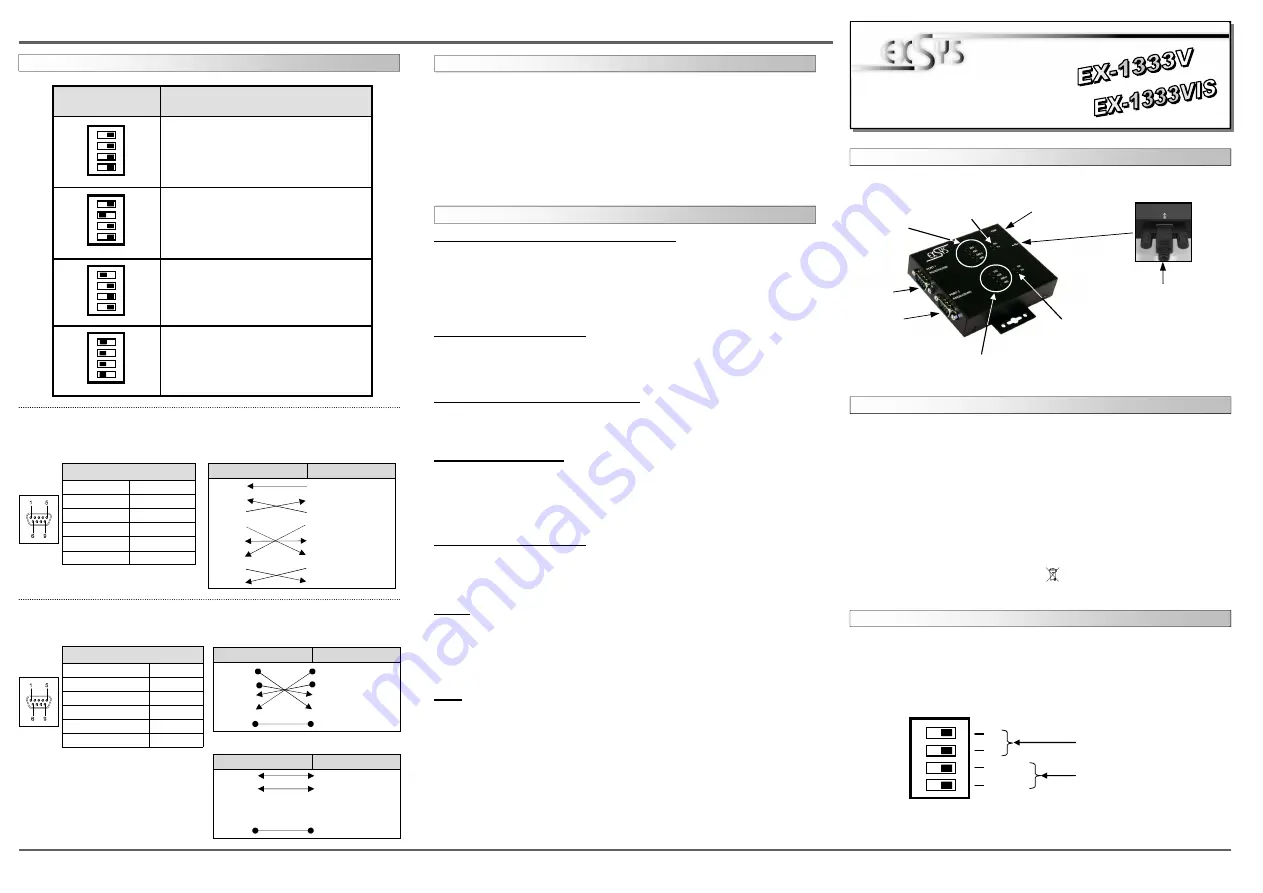
USB B-Anschluss
(verschraubbar)
Port 1 Mode LEDs
Port 2 Mode LEDs
Port 2
TX/RX LED
Betriebs LED
Port 1
TX/RX LED
Port 1
Port 2
Es gibt zwei 4-Pin DIP-Schalter auf der Rückseite der Metallbox für Port 1 und Port 2. Jeder hat
vier Schalter. Pin 1 und Pin 2 (markiert mit M1 und M0) hat die Funktion zwischen den drei
Modes RS-232, RS-422 und RS-485 umzuschalten. Pin 3 und Pin 4 (markiert mit TERM ON)
hat die Funktion die Abschlusswiederstände für die RS-422/485 Modes ein oder auszuschal-
ten.
1
2
3
4
O
N
M1
M0
TERM ON
TERM ON
RS-422/485 Mode
Schalter
Schalter für
Abschlusswiederstände
JUMPER SETTING & CONNECTORS
DIP-Switch
Description
RS485 2-wire mode
(Default)
RS485 4-wire mode
RS422 mode
RS232 mode
(Note: Both Pin 3 and Pin 4 have to be
set at OFF to work in RS232 Mode)
1
2
3
4
O
N
1
2
3
4
O
N
1
2
3
4
O
N
1
2
3
4
O
N
Serial 9 Pin D-SUB connector
Pin
Signal
Pin
Signal
1
CDC
6
DSR
2
RXD
7
RTS
3
TXD
8
CTS
4
DTR
9
RI
5
GND
DB 9M:
RS-232 Cable Wiring:
DB9 (EX-1333V)
RS232 (Peripheral)
1 DCD
1 DCD
2 RXD
2 RXD
3 TXD
3 TXD
4 DTR
4 DTR
5 GND
5 GND
6 DSR
6 DSR
7 RTS
7 RTS
8 CTS
8 CTS
RS-232 Pin Assignments:
RS-422/485 Pin Assignments:
Serial 9 Pin D-SUB connector
Pin Signal
Pin Signal
1 TXD- (DATA-)
6
NC
2 TXD+ (DATA+)
7
NC
3 RXD+
8
NC
4 RXD-
9
NC
5 GND
DB 9M:
RS-422 Cable Wiring:
DB9 (EX-1333V)
RS422 (Peripheral)
1 TXD-
1 TXD-
2 TXD+
2 TXD+
3 RXD+
3 RXD+
4 RXD-
4 RXD-
5 GND
5 GND
RS-485 Cable Wiring:
DB9 (EX-1333V)
RS485 (Peripheral)
1 DATA-
1 DATA-
2 DATA+
2 DATA+
3 RXD+
3 RXD+
4 RXD-
4 RXD-
5 GND
5 GND
HARDWARE INSTALLATION
Because there are large differences between PC’s, we can give you only a general installation
guide for the EX-1333V or EX-1333VIS. Please refer your computers reference manual whenever
in doubt.
1. Connect the USB cable (B-Plug) to the USB B-Port at the EX-1333V or EX-1333VIS.
2. After that connect the USB cable (A-Plug) to the USB A-Port at your PC.
3. Now you can set the mode via the DIP switch. (see picture jumper setting and connectors)
4. When you are ready you can start your PC and continue with the point Driver Installation.
Windows 2000/ XP/ Vista/ 7/ 8/ Server 200x
Windows will recognize a new „FT232R USB UART“ and open the hardware assistant. Please
choose manual installation and put the driver CD into your CD-ROM drive. Enter Path
"D:\USB_to_IO\FTDI\(32_64bit)Win7_8_XP_Vista_2008_2008R2_2003_2000”
into the box for the Path/Source and click at >next/continue<. Now Windows search for the
drivers in the specified directory. Follow the hardware assistant and finish the installation. If
Windows recognizes other new devices repeat the above described steps. Attention! Restart
Windows in any case after installing the drivers.
CHECK THE INSTALLED DRIVER
Click at Start<>Run< then enter “compmgmt.msc“ and click at >OK<. In the windows that
open select >Device Manager<. Under ”Ports (COM and LPT)“ you should find one more
new „USB Serial Port (COM2) to (COM3)“. If you see this or similar entries the module is
installed correctly.
CHANGE PORT NUMBER (NOT WIN98 & ME)
If you like to change the port number for example COM3 to COM5, open the >Device Manager<
click at >COM3<, >Settings< and then >Advance<. There you can choose between COM3 up to
COM256.
Windows 98/ 98SE/ ME
Windows will recognize a new “FT232R USB UART“ and open the hardware assistant. Please
choose manual installation and put the driver CD into your CD-Rom drive (as sample D:) . Now
enter the Path “D:\USB_to_IO\FTDI\Win98_ME” into the box for the Path/Source and click at
>next/continue<. Now Windows search for the drivers in the specified directory. Follow the
hardware assistant and finish the installation. If Windows recognizes other new devices repeat
the above described steps. Attention! Restart Windows in any case after installing the drivers.
CHECK THE INSTALLED DRIVER
Click at Start<>Run< then enter “compmgmt.msc“ and click at >OK<. In the windows that
open select >Device Manager<. Under ”Ports (COM and LPT)“ you should find one more
new „USB Serial Port (COM2) to (COM3)“. If you see this or similar entries the module is
installed correctly.
LINUX
There are drivers available for Linux. The drivers are located in the folder
“D:\USB_to_IO\FTDI\Linux x86_64“ on the driver CD. They are supported by the most ver-
sions of Linux. Because each individual distribution and kernel version of Linux is different,
sadly we cant provide a installation instruction. Please refer to the installation manual for stan-
dard I/O ports from your Linux version !
MAC
There are drivers available for MAC. The drivers are located in the folder
“D:\USB_to_IO\FTDI\MAC OSX or Mac_OS_9_8“ on the driver CD. They are supported by
the most versions of MAC OS. Because each individual version of MAC OS is different, sadly
we cant provide a installation instruction. Please refer to the installation manual for standard I/O
ports from your MAC OS version !


