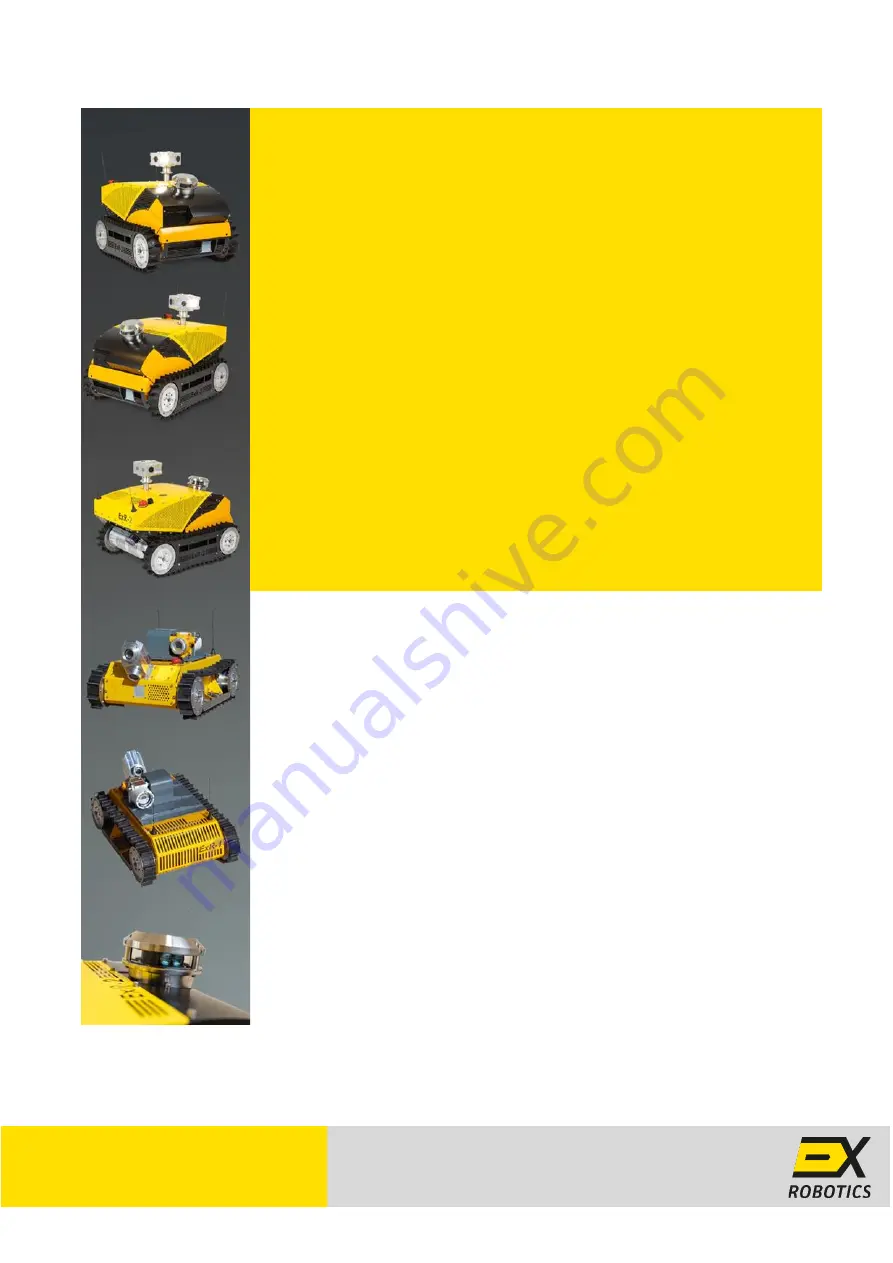
background image


Robot System 


Operating Guide 


LET’S DEPLOY ROBOTS 


TOGETHER 

ExRobotics B.V. 
Effenseweg 1 I 4838 BA Breda I The Netherlands 
[email protected] 

Summary of Contents for ExR-1

Page 1: ...Robot System Operating Guide LET S DEPLOY ROBOTS TOGETHER ExRobotics B V Effenseweg 1 I 4838 BA Breda I The Netherlands sales exrobotics global ...

Page 2: ...ing the document i e author Name Ian Peerless Job Title Director Signature Date 20th July 2021 Accountable Person who is accountable for the quality validity and timeliness of the document i e Process Owner Name Ian Peerless Job Title Director Signature Date 20th July 2021 Consulted on this document version Persons who have endorsed the document Names Ronald Schreurs Dorian Scholz Alberto Romay In...

Page 3: ...ed use of the Keep awake button Alarm if autonomous mission is interrupted Launching an autonomous mission explained Spot turn limitations expanded Corrected docking station electrical connections Simpler chili tags at waypoints explained Why doesn t my controller work How do I wash a contaminated robot 7 9 10 11 12 14 18 18 Ian Peerless 9 2019 10 16 Added video recording to remote control screen ...

Page 4: ...3 Tag Based Inspections 15 6 4 Full 3D Navigation 16 7 Operating Robots 20 7 1 Operative Training 20 7 2 Authorisation and Authentication 21 7 3 Customer support 21 7 4 Software releases 22 7 5 Routine Maintenance 22 7 6 Replacing tracks 22 7 7 Calibrating gas detectors 23 7 8 Replacing ExR 2 batteries 23 7 9 Changing ExR 2 SIM cards 24 7 10 Security 24 8 Questions and Answers 25 8 1 What is my ro...

Page 5: ...current version Copyright 2021 ExRobotics B V 8 9 Why does my robot drift to the left or right 27 8 10 Why have I experienced unexpected behaviour while operating a robot 27 8 11 How do I wash a contaminated robot 27 9 Robot and Docking Station Specifications 28 9 1 Worksite and Climate ExR 1 Robot 28 9 2 Worksite and Climate ExR 2 Robot Docking Station 28 9 3 Standard ExR 1 Specifications 29 9 4 ...

Page 6: ...ration of the robots especially with respect to their use in potentially explosive gas environments The others provide additional information about the robot systems and their use If there s a conflict between the documents the instructions will always prevail This operating guide Describes each key part of the robot system o Robots o Control stations that are used to communicate with the robot o ...

Page 7: ...eployed users will have little reason to interact with robots However the major components are shown on the drawings below Robot specifications are included in Section 9 ExR 1 Robot Platform ExR 2 Robot Platform The only controls mounted on each robot are the red emergency stop switch and the black on off switch When the red emergency stop switch is pressed downwards it immobilises the drive motor...

Page 8: ...in the inspection module panning It replaces the light in the inspection module panning Falco VOC module Up to 3 of these options can be installed on top of the hull Up to 2 of these options can be installed inside the hull Honeywell toxic gas module 3000 Mk II Honeywell toxic gas module Sensepoint XRL Simtronics hydrocarbon gas module Eaton MEDC DB20 speaker Not available COMING SOON Det tronics ...

Page 9: ...ssion the operative should approach the docking station in slow speed mode and in the direction indicated in the diagram below Provided the robot is reasonably straight and central when approaching the docking station the robot will automatically align the induction charging plates using the plastic strips under its hull To facilitate robot alignment the robot should approach the docking station i...

Page 10: ...rs 30 minutes to warm up before starting a mission see their instructions A power socket module when fitted enables the robot to be charged within 3 hours This requires the robot to be manually plugged into a power supply using a quick charger that can be ordered with the robot The quick charger s lead is typically 3 meters long If the robot is docked you should first switch off power to the induc...

Page 11: ... use the cursor to select the area of interest and click on the Accept button to capture the image Alternatively you can take a full size picture without selecting the POI icon Snapshots are displayed in the Media Log once they have been uploaded to the server this happens automatically after taking them and can be viewed in large scale by clicking on them From there they can be saved to the local...

Page 12: ...t won t sleep If it s unticked the robot will save 4G costs and battery power by sleeping whether or not it s docked Select a mission using the drop down box To launch the mission click on the Play button to the left of the mission drop down box to cancel the mission press the button again Missions will usually be started when the robot is in a docking station However it s also possible to launch ...

Page 13: ...t of the screen They can report issues to our engineers using the Feedback option in the user menu to the top right of the screen The gamepad controls are illustrated below The green button activates remote control by enabling the gamepad and drive motors The blue button switches from remote control to autonomous driving The yellow button deactivates remote control by disabling the gamepad The red...

Page 14: ... levels were below the lower alarm level amber where they were between the two alarm levels and red where they were above the upper alarm level Section Error Reference source not found describes how to set the alarm levels Other information that has been gathered at Waypoints is displayed in the right hand part of the screen Snapshots and gas readings are uploaded immediately Other recordings are ...

Page 15: ...ra or sensor is targeted Examples of POIs are valves flanges and pumps To target the POI the robot will usually need to change its azimuth rotate and in some cases will require a camera to lift its field of view elevate There can be more than one action at a POI Waypoints are 2D locations from which POIs are observed There can be multiple POIs at a waypoint In Line following navigation waypoints a...

Page 16: ...3 Tag Based Inspections 1 Launch an autonomous mission from the Robot Control screen and stop the mission a few meters before the waypoint at which actions are to be performed with the orange line visible from the floor cam 2 Open the Mission Editor screen 3 Click on Create Mission and give a name 4 Click on Add new action and press the play button The robot will drive to the tag and stop between ...

Page 17: ...n see Section Error Reference source not found Actions will be recorded in the mission report 6 4 Full 3D Navigation This is only available for ExR 2 robots The robot can drive without the need of physical guidance such as a line Using its 3D sensors the robot can extract geometrical information of the surrounding environment The robot can be used to record this environment so that it can learn ho...

Page 18: ...21 07 20 Page 17 of 30 This document is considered an uncontrolled copy when printed Always ensure that you print and use a current version Copyright 2021 ExRobotics B V 5 Click on yellow button Create Mission 6 Give a unique name and click Create 7 Add a new route by clicking on the grey button Add new route ...

Page 19: ...ntil you reach your first waypoint 11 You have three options photo video or waypoint 12 For photos and videos you may need to rotate the inspection module panning as described in Section 5 2 Once the POI is in the Field of View FoV you can take a video a full size picture or a framed picture as described in Section 5 2 Then give a name to the POI possibly a tag number and click on Add action 13 Fo...

Page 20: ...nd use a current version Copyright 2021 ExRobotics B V 17 Click on the red button to stop recording the mission 18 Accept the confirmation dialog 19 Your mission is now saved 20 Drive over the docking station to charge the robot and wait for the Mission Active box the get unticked For the robot to repeat the taught mission 1 Change to the Driver Screen 2 Select the mission from the Robot Control l...

Page 21: ...or backwards motion The robot isn t designed to climb stairs or gradients above 30 degrees It may topple over It can however cross steps up to 20cm ExR 1 and up to 10cm ExR 2 Approach them perpendicularly The downward facing camera can enable precise positioning The warranty doesn t cover impact damage The robot must be returned to the docking station at the end of a mission and before the battery...

Page 22: ...s Fleet Managers will control access with the User Management screen see below which is accessed from the User Menu see Section 5 1 When a new user is registered they will receive an E Mail that will prompt them to change their password before full access is granted It s then possible to connect to robots by visiting this address using Google Chrome https login energy robotics com 7 3 Customer sup...

Page 23: ...be cleared of debris and leaves The robot will be inspected for visible damage In particular if the wire antennas are too bent they should be replaced New wires must be sourced from ExRobotics to maintain the robot s Ex status They screw onto their bases The tracks will be checked for visible wear and obstructions They ll be replaced if necessary The gas detectors if fitted will be calibrated at t...

Page 24: ...and side of robots which is secured with two hexagonal socket head screws see picture ExR 2 gas sensors are accessed by removing the upper cladding 7 8 Replacing ExR 2 batteries ExR 2 s batteries can be replaced by removing the front hull cladding and the battery pack lid behind When replacing the batteries make sure that Only batteries supplied by ExRobotics are used Any other batteries will inva...

Page 25: ...p hull plate Remove the front of the communications module s front enclosure Change the SIM Make sure you do not damage the flameproof joint surfaces around the front enclosure and back enclosure Also ensure that the O Ring is correctly seated Re torque the bolts securing the front to the back enclosures to 7 Nm with a calibrated torque wrench ExRobotics will provide remote support the first time ...

Page 26: ... robot connects to the server before it s deployed Therefore connection issues are often because the control station hasn t connected to the server The most common reason is that a customer firewall has blocked access The connection to the robot consists of two types one for the control commands via HTTPS over TCP and one for very low latency video signals via WebRTC over UDP To be able to control...

Page 27: ...riven continuously 7 hours if it s static with its sensors on but no lights Usually a robot should be stored on its docking station when not in use so it will be charged via its induction charger However sometimes this isn t possible e g during transport In this case a full ExR 1 battery pack will last 2 years if the robot is switched off using its black on off switch 2 days if it s static and asl...

Page 28: ...behaviour while operating a robot If this occurs Press F12 immediately after the event occurs Click on the Console tab that appears Right click somewhere in the console window and select Save as from the Context menu Use the Feedback option on the Driver s screen to send the file and an explanation to our engineers 8 11 How do I wash a contaminated robot You can use a water jet spray to wash the r...

Page 29: ...eight Change Essentially level site with ledges 20 cm high and slopes 35 steep Corrosion Erosion Maritime conditions Precipitation Rain light snow and standing water Light conditions Day and night 9 2 Worksite and Climate ExR 2 Robot Docking Station Description Specification Operating Temp Range 40C to 55C depending on options 40C to 50C if fitted with Pepperl Fuchs switches Equip Protection Level...

Page 30: ...ownwards facing 1 2 MP digital video camera All with live video transmission to web browser interface Zoomed still images and video recordings can be taken and downloaded from the web browser interface Light module 3 x 690 Lm LED lights illuminate the fields of view of the 3 cameras Microphone Mono microphone transmits sound to the web browser interface Crowcon methane gas module Standard for Emis...

Page 31: ...terface Zoomed still images and video recordings can be taken and downloaded from the web browser interface Drive camera module Forwards downwards facing 1 2 MP digital video camera 690 Lm LED with the same functionality as the inspection module panning optical Microphone Mono microphone transmits sound to the web browser interface Remote control Remote control via Energy Robotics cloud with audio...

Reviews: