background image


Instruction Manual 

16/9/4 Channel Digital Video Recorder 


EDVR SERIES


Summary of Contents for EDVR16D1/250

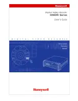
Page 1: ...Instruction Manual 16 9 4 Channel Digital Video Recorder EDVR SERIES ...

Page 2: ...nstructionGuide 2005 EverFocus Electronics Corp www everfocus com All rights reserved No part of the contents of this manual may be reproduced or transmitted in any form or by any means without written permission of the Everfocus Electronics Corporation Release Date May 2008 ...

Page 3: ...off and on the user is encouraged to try to correct the interference by one of the following measures Reorient or relocate the receiving antenna Increase the separation between the equipment and receiver Connect the equipment into an outlet on a circuit different from that to which the receiver is connected Consult the dealer or an experienced radio TV technician for help FCC Caution Any changes o...

Page 4: ...A digital device The changes or modifications not expressly approved by the party responsible for compliance could void the user s authority to operate the equipment In a domestic environment this product may cause radio interference In which case the user may be required to take adequate measures ...

Page 5: ...Date Setup Menu 17 3 2 Camera Setup Menu 21 3 3 Record Setup Menu 26 3 4 Alarm Setup Menu 28 3 5 Motion Setup Menu 31 3 6 VIDEOLOSS Setup Menu 34 3 7 Network Setup Menu 36 3 7 1 CONFIG 36 3 7 2 ALARM NETWORK 38 3 7 3 EMAIL 39 3 7 4 PASSWORD 41 3 7 5 PPPoE 42 3 7 6 DDNS 43 3 8 Schedule Setup Menu 44 3 9 Disk Setup Menu 46 3 10 Control Setup Menu 48 3 11 Warning Setup Menu 50 3 11 1 FAN FAULT 50 3 1...

Page 6: ...bnet Masks 78 10 3 Gateway Address 79 10 4 Virtual Ports 79 10 5 Pre Installation 80 10 6 What Type of Network Connection do you have 81 10 7 Simple One to One Connection 82 10 8 Direct High Speed Modem Connection 88 10 9 Router or LAN Connection 90 11 LINKSYS PORT FORWARDING 93 12 D LINK PORT FORWARDING 97 13 DDNS 101 13 1 Creating a DDNS Account 101 14 VIEWING THROUGH INTERNET EXPLORER 103 14 1 ...

Page 7: ...NDIX B ALARM BOARD CONFIGURATION 124 APPENDIX C RJ45 RS485 PIN ASSIGNMENT 127 APPENDIX D LAPSE MODE RECORDING TABLE 128 APPENDIX E INSTALLATION STEPS OF NERO INCD SOFTWARE 132 INDEX 141 TROUBLESHOOTING 143 ...

Page 8: ...vice The changes or modifications not expressly approved by the party responsible for compliance could void the user s authority to operate the equipment Note This is a class A product In a domestic environment this product may cause radio interference In which case the user may be required to take adequate measures Notice The information in this manual was current when published The manufacturer ...

Page 9: ...or moisture not try to operate it in wet areas Do take immediate action if the appliance becomes wet Turn the power off and refer servicing to qualified service personnel Moisture may damage the appliance and also cause electric shock Do not use strong or abrasive detergents when cleaning the appliance body Use a dry cloth to clean the appliance when it is dirty When the dirt is hard to remove use...

Page 10: ...ple near a bath tub wash bowl kitchen sink or laundry tub in a wet basement near a swimming pool in an unprotected outdoor installation or any area which is classified as a wet location Servicing Do not attempt to service this unit by yourself as opening or removing covers may expose you to dangerous voltage or other hazards Refer all servicing to qualified service personnel Power Cord Protection ...

Page 11: ...on Detection Capabilities for each camera 28 22 Support RS485 for PTZ and or control keyboard Built in real time clock and Auto Time Synchronization with global NTP server through Internet F Serial without DVD Built in up to Four 3 5 IDE Hard Disks can be added D Serial with DVD RW Built in up to Two 3 5 IDE Hard Disks can be added Ethernet Interface for Remote Network Viewing and Controlling Shut...

Page 12: ...f alarm output Hard Disk Storage F series up to 4 internal 3 5 IDE Hard Disks D series up to 2 internal 3 5 IDE Hard Disks External Storage SCSI connector for use with EDA800 External Hard Drive Array D3 series only Recording Rate Please refer to Note at the following page Recording Mode Normal Schedule or Event recording Motion Video Loss Alarm Playback Rate Up to 60 50 Images per second for NTSC...

Page 13: ...ntrol keyboard Power Source AC 100 240V Power consumption D series 50W F series 70W Dimension 17in W x 15 8in D x 2 8in H Weight 14 15 lb Operating Temperature 32o F 104o F NOTE Recording Rate Model NTSC PAL EDVR16D1 F1 EDVR9D1 F1 EDVR4D1 F1 D1 720x480 30 IPS Half D1 720x240 60 IPS CIF 360x240 120 IPS D1 720x576 25 IPS Half D1 720x288 50 IPS CIF 360x288 100 IPS EDVR16D2 EDVR16F2 D1 720x480 60 IPS ...

Page 14: ...he playback picture 5 SEARCH Press this key to enter the SEARCH MENU 6 COPY Opens image export menu In playback mode the current playback position is stored as image export start position 7 ENTER Press this key to enter items or jump to next subentry in the menu setting 8 DISPLAY Press this key to switch display of channels display color of channels Black Red Yellow Pink Blue and White are availab...

Page 15: ...OOM In full screen mode 2x electronic zoom Zoom screen can be moved through JOG Enter key changes the direction Pressing the zoom key again switches the electronic zoom off In multiscreen mode Image orientation adjustment Use the JOG to adjust the image to the respective monitor type ENTER switches between horizontal and vertical adjustment Press the zoom key again to exit screen adjustment 12 SEQ...

Page 16: ...ward rewind the video frame by frame In the Menu mode turn the Jog dial to change settings and values in subentries 16 System LEDs LEDs for system active HDD ALARM and LAN display Note External HDD LED will only be light on for EDVR16D3 model 17 Channel Key 1 16 Press channel key CH1 CH16 to display that channel in full screen view 18 Mouse For connecting the mouse 19 DVD RW Burner DVD RW burner o...

Page 17: ...r off 3 MAIN MONITOR This connector is used for the main monitor display a number of different display modes may be selected for viewing 4 CALL MONITOR This connector is used for the call monitor This monitor can only display a full screen but not able to enter Setup Menu POWER MONITOR For models EDVR16D1 F1 EDVR16D2 F2 EDVR9D1 F1 EDVR4D1 F1 For model EDVRD3 ...

Page 18: ...type alarm signal inputs The Alarm Input can be selected as normal open N O or normal close N C input in the ALARM SETUP MENU When an alarm occurs alarm recording will automatically start ALM OUTPUT A built in relay offers 3 nodes which are ALM COM common ALM NO normal open and ALM NC normal close for external use Note Please check APPENDIX B to see other available alarm input output functions LAN...

Page 19: ...ding and it can be enabled by setting to YES or NO in the RECORD SETUP MENU Audio OUT Connect an audio output to a monitor or other device Audio 1 corresponds to CH 1 audio 2 corresponds to CH 2 audio 3 corresponds to CH 3 and audio 4 corresponds to CH 4 SCSI Only available for EDVR16D3 13 SCSI Connector For connecting the optional external hard drive array EDA800 S VIDEO Only available for EDVR16...

Page 20: ... events on each screen There are a total of 6 different signals Alarm event Alarm event shows on a channel if an ALARM is enabled for that camera in the ALARM SETUP MENU and an alarm is triggered Motion event Motion event only shows up when the camera s MOTION is enabled in MOTION SETUP MENU and the camera detects movement Video loss event Video loss event only shows when the camera s VIDEOLOSS is...

Page 21: ...uld like to change camera and then press channel key on the front panel to choose that channel Press SELECT again to exit from this mode 4 Play status bar The play status bar appears in play back mode if you enable a status bar on the screen Please see DISPLAY 8th item of Front Panel Keypads There are three parts that will be shown play date play status and play time 1 Play date The date on which ...

Page 22: ... R01 16 currently recording on HDD 1 16 full 3 Event The current last event that occurred 4 Current time The current time which is set in the TIME DATE SETUP MENU 5 Audio Ch Displays which audio channel is currently active This can be changed by turning the Jog wheel in the live camera mode 6 HDD Fan status No Disk only shows when no disk is installed or detected No Fan only shows when internal fa...

Page 23: ... or system installers 2 2 1 1 P Pa ac ck ki in ng g Please check accessories in the packing before installation 2 2 2 2 S Sy ys st te em m F Fl lo oo or rp pl la an n Please refer to the following diagrams for the system connections Note Monitor and Camera must be purchased separately Diagram 2 1 Chapter 2 ...

Page 24: ...put Connect the speaker or other audio listening devices to the audio output terminal on the back of the digital video recorder 5 Ethernet The digital video recorder may be viewed from a PC via the LAN connector using a RJ45 Ethernet cable 6 RS232 9 pin Sub D control input output for service purpose 7 RS485 The digital video recorder can be controlled from a keyboard or a speed dome via RS485 Note...

Page 25: ...isplay one full screen camera at a time 2 2 4 4 F Fi in na al l I In ns st ta al ll l P Pr ro oc ce es ss s Once you have completed the basic wiring installation and the hard disk drive installation you are ready to turn on the DVR Simply plug the power source you installed earlier The POWER LED lights will light up if power is normal The next step is to set up the menu options for the DVR ...

Page 26: ...s process press the MENU key Once inside the main menu you will find there are 12 setup option pages as follows Press the MENU key to enter or exit the MAIN SETUP MENU Press the MENU key in any sub menu to go back to previous screen Dial the Jog clockwise or counterclockwise to scroll through the MAIN MENU options or to change subentry values Press the ENTER key to go to the next subentry in a men...

Page 27: ... savings as well as synch it with an internet based time server In the TIME DATE SETUP MENU the following fields are defined as follows 1 TIME FORMAT This field represents the time format on the DVR You can select between 12 HOUR and 24 HOUR format 2 TIME This field represents the current time on the DVR To change this simply use the Jog Dial on the DVR The Time is represented as follows Hour 00 2...

Page 28: ...zone you need to disable daylight saving first Enable the daylight saving after finish setting the time zone Note Please double check your current Time on DVR again after setting Daylight Saving ON If you are currently in daylight saving time period then Daylight saving time may be over adjusted as DVR will adjust daylight saving time even though you have already set the current time which is dayl...

Page 29: ...ype cmd and press OK To set the starting time change of daylight saving time Choose the FROM time and TO time when daylight savings starts 7 END TIME To set the end time of daylight saving time To set the ending time change of daylight saving time Choose the FROM time and TO time when daylight savings ends To set the end week of daylight saving time Dial the jog to set the end week To set the end ...

Page 30: ...MT Central Daylight Time subtract 5 hours from GMT Central Standard Time subtract 6 hours from GMT Mountain Daylight Time subtract 6 hours from GMT Mountain Standard Time subtract 7 hours from GMT Pacific Daylight Time subtract 7 hours from GMT Pacific Standard Time subtract 8 hours from GMT Alaska Daylight Time subtract 8 hours from GMT Alaska Standard Time subtract 9 hours from GMT Hawaii Aleuti...

Page 31: ...ou to assign a title to each camera input Each channel supports a title with up to 12 characters Press Enter to move to each character and use the Jog Dial to change the value The available alphanumeric characters are 0 1 2 3 4 5 6 7 8 9 A B C D E F G H I J K L M N O P Q R S T U V W X Y Z and an empty space 2 PTZ ID Select PTZ ID Address from 001 255 or OFF OFF is the same as 000 The default value...

Page 32: ...ell time for either the Main or Call Monitor sequence You can set any time from 01 99 on Main or 00 99 on Call To change this simply use the Jog Dial on the DVR 5 REC QUALITY Select an image quality for recording There are six different qualities available A higher image quality needs more HDD space To change this simply use the Jog Dial on the DVR The approximate space needed per image is listed ...

Page 33: ... the Record button If you have set Time Period in Schedule Setup Menu then there will be a star sign beside that TP in Camera Setup Menu NORMAL IPS recording rate for manual or scheduled recording and recording triggered through REC IN input contact The maximum image rate is limited to the maximum recording rate divided by the number of installed cameras Max DVR recording rate depends on recording...

Page 34: ...s setting correlates closely with Motion Setup If motion setting is disabled motion detection will not function regardless if TP Time Period Action in Camera Setup Menu is ON or OFF However if Motion setting is enabled then motion detection function works depending on Action setting in Camera Setup Menu All motion actions including buzzer relay network alarm e mail and log will be triggered if the...

Page 35: ...tting from a camera to other cameras In order to quickly copy the setting from one camera to other cameras we provide a copy function for camera settings Highlight the desired camera from the list on the left and then press COPY COPIED will show up in the top right corner of the screen Dial the Jog to the camera you would like to copy to and then press SEARCH to paste The previous settings of the ...

Page 36: ...rded when machine is recording and a microphone is present NO Audio will not be recorded when machine is recording 2 TIME STAMP ON The time stamp will be recorded on the video and picture when recording OFF The time stamp will not be recorded on the video and picture when recording 3 TIME STAMP POSITION BOTTOM The time stamp will be recorded on the bottom TOP The time stamp will be recorded on the...

Page 37: ...88 240 200 D3 720 x 480 720 x 576 120 100 6 RECORD MODE REWRITE Continuous recording Disk will be overwritten if it is full STOP Stop recording when disk is full 7 AUTOWRITE WITHIN You can set DVR to automatically overwrite after the selected number of days If you do not wish to use this function simply select 0 8 PRE ALARM RECORDING Select YES to enable pre alarm recording function Select NO to d...

Page 38: ... the following fields are defined 1 ALARM This field is to turn alarm detection ON or OFF The default value is ENABLE To change this simply use the Jog Dial on the DVR ENABLE Enable alarm detection DISABLE Disable alarm detection 2 ALARM TYPE This field is to change the type of alarm recording The default value is N O To change this simply use the Jog Dial on the DVR N O Normal Open alarm N C Norm...

Page 39: ...ion simply select OFF 6 DURATION 1 99 SEC The amount of time alarm recording screen change buzzer and output contact will last Adjustable from 1 99 seconds TRANSPARENT Continuous recording screen change buzzer and output contact for an alarm event 7 ALARM OUTPUT This will transmit a signal to another device The setting of alarms are NONE not activated 1 output signal 1 transmits 2 output signal 2 ...

Page 40: ...display when an alarm occurs SEQUENCE Display in sequence mode on call monitor when an alarm occurs according to sequence duration set in Camera Setup Menu ACTIVE CAMERA Display the active camera in full screen mode to the call monitor when an alarm occurs 13 SUMMARY Dial Jog to change items in the SUMMARY table All alarm s statuses are shown in SUMMARY tables These tables are for checking alarm o...

Page 41: ...he MOTION SETUP MENU the following fields are defined as follows 1 MOTION This field is to turn motion detection on or off The default value is DISABLE To change this simply use the Jog Dial on the DVR ENABLE Enable motion detection DISABLE Disable motion detection Note Motion only works in live and playback modes It is invalid while in menus 2 SENSITIVITY The sensitivity allows users to adjust to...

Page 42: ...RM EMAIL YES Send an email when an alarm occurs NO Do not send an email when an alarm occurs The email address and email server can be set in the NETWORK SETUP MENU 7 ALARM NETWORK YES Enable alarm network when an alarm occurs NO Disable alarm network when an alarm occurs 8 BUZZER Audible buzzer when motion is detected ENABLE To enable a motion buzzer DISABLE To disable a motion buzzer 9 MOTION DE...

Page 43: ...otion is detected To clear the motion entire area Press PLAY to clear the entire motion area If you forget the motion grid commands Press CALL to display a hint window shown below In the motion edit mode The default motion area of each camera is entire screen which displays in light green Press COPY or left click the mouse to start setting an area Use the JOG Dial to move the cursor Press ENTER to...

Page 44: ...P MENU the following fields are defined as follows 1 VIDEOLOSS ENABLE Enable video loss detection DISABLE Disable video loss detection 2 LOG YES Select YES if you wish to record Video Loss Events in the Log NO Select NO if you do not wish to record Video Loss Events in the Log 3 DURATION Duration of VIDEOLOSS buzzer ranges from 1 sec to 99 seconds The default value is 5 seconds To change this simp...

Page 45: ... sending an email when Video Loss event occurs The email address can be set in the NETWORK SETUP MENU 6 BUZZER Audible alarm buzzer ENABLE To enable a VIDEOLOSS buzzer DISABLE To disable a VIDEOLOSS buzzer 7 ALARM NETWORK YES Enable alarm network NO Disable alarm network 8 SUMMARY All video loss s statuses are shown in SUMMARY tables These tables are for checking video loss overall statuses but no...

Page 46: ... about network setup please refer to Chapters 10 13 of this manual to fully understand how to setup your network for this DVR In the NETWORK SETUP MENU the following fields are defined as follows Note Since every Network Configuration is different please contact your Network Administrator or ISP for details on assigning IP addresses and port numbers 3 7 1 CONFIG In the CONFIG of the NETWORK SETUP ...

Page 47: ...n the DVR When DHCP is selected the DHCP server will assign this value automatically 4 GATEWAY This field is to set the gateway for your network so the DVR will be recognized within the network To change this simply use the Jog Dial on the DVR When DHCP is selected the DHCP server will assign this value automatically 5 DNS SERVER This field is to set the DNS server for your network so the DVR will...

Page 48: ...e 37260 37263 on your router 10 BW CONTROL This configuration allows user to control the bandwidth of DVR 11 MAC ADDR This field is for those Internet service providers or Network administrators who require a MAC address of the network card of the DVR This option cannot be changed 3 7 2 ALARM NETWORK Diagram 3 11 Note Since every Network Configuration is different please contact your Network Admin...

Page 49: ... protocol UDP communicate with client via UDP protocol 2 PORT NUMBER Set the communication port with Alarm server 3 UNIQUE ID Set the ID number of your DVR to Alarm server 4 SERVER 1 Assign the IP address of Alarm server 1 5 SERVER 2 Assign the IP address of Alarm server 2 6 SERVER 3 Assign the IP address of Alarm server 3 3 7 3 EMAIL Diagram 3 12 ...

Page 50: ...PASSWD Input the password if the SMTP server requires Authentication 6 RECEIV EMAIL ADDR Input the e mail address for receiving e mail messages when the EVENT is enabled and triggered Example In Motion Setup Menu if the EMAIL NETWORK is set to YES this e mail address will receive a message and a still image in ARV format from the DVR when Motion is triggered This ARV file can be played back by ope...

Page 51: ...IN The default Password 11111111 numeric only To change this press Enter to move to each character and use the Jog Dial on the DVR to change each character There are 3 level types 1 Admin User has all the rights including viewing live video performing a search playback and controlling the PTZ camera if one is connected 2 Play User has the same rights as Admin user Except PTZ programming and Remote...

Page 52: ...SP for PPPoE connection 3 PRIMARY DNS IP address of DNS server that is provided by ISP 4 SECONDARY DNS If your ISP provides you with a secondary DNS address please set it in here NOTE Please complete all settings in the PPPoE Setup Menu before changing IP CONFIG to PPPoE in the CONFIG options If you make this change before completing PPPoE settings then the PPPoE function will not work ...

Page 53: ...S of the NETWORK SETUP MENU we define 1 SERVER DDNS provider example www dyndns com 2 USER User name of the account 3 PASSWD Password of the account 4 RECORD ID Identity tag used by certain DDNS providers 5 FQDN The domain name of this account ...

Page 54: ...DNS account that the user applies will likely differ from this example See Chapter 13 for more details 3 3 8 8 S Sc ch he ed du ul le e S Se et tu up p M Me en nu u Diagram 3 16 Diagram 3 16 is a screen shot of the SCHEDULE SETUP MENU In this menu you can set a unique timer any day of the week to start recording from a specified start time to an end time This menu works together with the camera me...

Page 55: ...time you wish to start the timer recording To change this simply use the Jog Dial on the DVR Hour 0 23 in 24 hour time format 1 12 in 12 hour time format Minutes 00 59 3 END This field is used to set the time you wish to stop the timer recording To change this simply use the Jog Dial on the DVR Hour 0 23 in 24 hour time format 1 12 in 12 hour time format Minutes 00 59 Note To record all day long s...

Page 56: ...s selectable from 1 up to 50 disks in intervals of 4 The total number of hard drives varies by model 2 DISK VIDEO DELETE Press SELECT to start delete A delete disk confirmation window will show up after pressing SELECT button Dial the Jog to move highlighter to YES and then press SELECT button a deleting indicator DELETE will show up An indicator of success SUCCESS will show up when delete is comp...

Page 57: ... scale of the disk 4 NO Shows the hard drive number The number of disks displayed may vary depending on the model Note For EDVR16D3 model up to 50 hard drives can be added through SCSI port 5 SIZE Storage capacity of the hard drive 6 C or F Current temperature of the hard drive in Celsius or Fahrenheit degrees 7 START END TIME Shows the date and time range stored on the hard drives ...

Page 58: ... the RS232 port on the DVR There are six different speeds 2400 BPS 4800 BPS 9600 BPS 19200 BPS 38400 BPS and 57600 BPS The default setting from the factory is 9600 BPS To change this simply use the Jog Dial on the DVR 2 RS232 Stop Bit This field is to set the stop bit for the RS232 connection There are two different stop bits 1 or 2 The default in the DVR is set to 1 To change this simply use the ...

Page 59: ...erent stop bits 1 or 2 The default in the DVR is set to 1 To change this simply use the Jog Dial on the DVR 7 RS485 Parity This field is to select the parity level at which you will be connected You can choose between None Odd or Even parity levels Default is set to none To change this simply use the Jog Dial on the DVR 8 RS485 Data Bit This field is the data bit at which you will be transferring ...

Page 60: ... BUZZER Fan buzzer To change this simply use the Jog Dial on the DVR ENABLE To enable a buzzer when the fan does not work DISABLE To disable fan buzzer 2 ALARM OUTPUT This will transmit a signal to another device The setting of alarms are NONE not activated 1 output signal 1 transmits 2 output signal 2 transmits 3 output signal 3 transmits and 4 output signal 4 transmits To change this simply use ...

Page 61: ...NO Do not send an email when the fan does not work The email settings can be set in the NETWORK SETUP MENU 3 11 2 HDD TEMP Diagram 3 20 In HDD TEMP we define 1 BUZZER HDD TEMPERATURE buzzer ENABLE To enable a buzzer when HDD s temperature is higher than the temperature set in SET TEMPERATURE DISABLE To disable HDD TEMP Buzzer ...

Page 62: ... ALARM YES To enable network alarm NO To disable network alarm 5 SEND EMAIL YES Send an email when HDD s temperature is overheated NO Will not send an email when HDD s temperature is overheated The email settings can be set in the NETWORK SETUP MENU 6 STOP RECORD YES Stop recording when HDD s temperature is overheated NO Will not stop recording even when HDD s temperature is overheated 7 SET TEMPE...

Page 63: ...vated 1 output signal 1 transmits 2 output signal 2 transmits 3 output signal 3 transmits and 4 output signal 4 transmits To change this simply use the Jog Dial on the DVR Only EDVR16D3 model has 4 alarm outputs All others have only 1 alarm output 3 ALARM DURATION The length of time the buzzer remains active This can be set from 1 sec to 99 seconds or permanent The default value is 5 seconds 4 NET...

Page 64: ...HDD FULL buzzer ENABLE To enable a buzzer when HDD is full DISABLE To disable HDD Full buzzer 2 ALARM OUTPUT This will transmit a signal to another device The setting of alarms are NONE not activated 1 output signal 1 transmits 2 output signal 2 transmits 3 output signal 3 transmits and 4 output signal 4 transmits To change this simply use the Jog Dial on the DVR Only EDVR16D3 model has 4 alarm ou...

Page 65: ...n email when HDD is full NO Will not send an email when HDD is full The email settings can be set in the NETWORK SETUP MENU 3 3 1 12 2 S Sy ys st te em m S Se et tu up p M Me en nu u Diagram 3 23 Diagram 3 23 is a screen shot of the SYSTEM SETUP MENU This menu is for setting up any additional options and restoring defaults to the digital recorder In the SYSTEM SETUP MENU the following fields are d...

Page 66: ...ce must be inserted properly before choosing the LOAD or SAVE options System will ask you to stop recording if you try to access any of these options while the system is recording NO Press ENTER key to move to next option 4 UPDATE SYSTEM SOFTWARE Turn the jog to enter the selection window YES Press SELECT on YES to update system software from USB NO Press SELECT on NO to cancel updating Note Syste...

Page 67: ...f you set a quick play time shorter than this the video will not be played because the video files are not yet stored to HDD 7 SYSTEM PASSWORD ENABLE YES Select YES to enable the password function NO Select NO to disable the password function 8 PASSWORD and RIGHTS The different login passwords indicate the different level of users and no login name is necessary Each number will appear instead of a...

Page 68: ... NO STOP OK NO NO NO REC OK NO NO NO PAUSE OK NO NO NO ALARM RESET OK OK NO NO Note 1 If the passwords of different levels are set the same you will enter a higher level when you login For example you will login to ADMINISTRATOR level if the password of ADMINISTRATOR and GENERAL levels are the same 2 After exiting to the live camera view and waiting 60 seconds the system will automatically log out...

Page 69: ...at event 4 4 1 1 I In ns st ta an nt t N N R Re ec co or rd di in ng g S Se et tu up p Press the Record key to start recording immediately When REC is pressed the pictures being monitored will be recorded in the HDD The recording quality and recording speed can be set in the CAMERA SETUP MENU To set the target camera for a particular recording speed IPS when using the instant record method apply t...

Page 70: ...CHEDULE SETUP MENU Diagram 4 1 Please refer to SCHEDULE SETUP MENU for setting procedure and more details 4 4 3 3 E Ev ve en nt t R Re ec co or rd di in ng g S Se et tu up p We will now define two event recording types ALARM and MOTION After the event recording is enabled the DVR will start an event recording when an event occurs For instance when motion activity or alarm action is detected by the...

Page 71: ...ample you can enable motion on Camera 2 in the MOTION SETUP MENU as shown below You can enable multiple alarm or motion triggers Diagram 4 2 2 When the event is set enter the CAMERA SETUP MENU to set the event recording speed PS of the camera in the time period TP section Diagram 4 3 ...

Page 72: ... MENU 2 If the recording speed is changed while the machine is recording the new recording speed will not take effect until recording is stopped completely DVR provides a record function which is triggered by external signal via the 19th pin of the ALARM INPUT OUTPUT port When the record input signal is triggered constantly DVR will start to record according to the speeds set on Time Period TP N T...

Page 73: ...M SETUP MENU The DVR is duplex which means you can record and playback the same time 1 Playback Press the STOP key to stop playing back PLAY STOP 2 Stop 3 Fast Forward Reverse Playback While in playback turn the Shuttle dial clockwise to begin fast forward playback Turn the Shuttle dial counterclockwise to begin fast reverse playback The speed will be shown on the status bar of the bottom screen T...

Page 74: ...bottom screen The available speeds are 1 2 1 4 1 8 1 16 and 1 32 You can either manually hold the shuttle dial in the position or press ENTER while holding the dial to lock the speed that is desired PAUSE 5 Image advance Forward Reverse PAUSE Press PAUSE key to freeze the picture Turn the Jog dial clockwise to advance the still video image by image Turn the Jog dial counterclockwise to rewind the ...

Page 75: ...in search menu setting and press the CALL key to go to previous subentry in search menu setting Press MENU to exit Press SELECT or the tilt wheel of the mouse to start search 1 TIME DATE Search Playback A SEARCH MENU will show up after pressing SEARCH key Select BY TIME DATE and then select the start date time you want to search Then select the camera number and Disk Number to be searched Lastly p...

Page 76: ...oving to next page dial Shuttle counterclockwise or press CALL for moving to previous page If you would like to jump to a specific page directly you can press Search then dial Jog to the page and press Enter Dial the Jog to scroll through events on the list When the desired item is highlighted press ENTER to play the selected event Note If there is no video stored in the date time specified then t...

Page 77: ...rting point of HDD s disk space PL a Power Loss event RTn a power return event in a schedule recording mode n Time Period 1 8 RTN a power return event in Normal Instant recording mode RUn record of Remote User login through Internet Explorer n user 1 6 Tn a scheduled Time Period recording event n Time Period 1 8 TN a Normal Instant recording event Vn a Video loss event n channel number DLB Begin D...

Page 78: ...the recorder Insert the USB pocket driver into the USB slot on the front panel or a formatted DVD RW disc into the DVD drive USB slot DVD drive Digital Video Recorder allows users to select the camera for copying image video to movie file or copying DVRViewer which is the image video player The camera title will be displaying at the top of the screen Chapter 6 COPY Press COPY key in live mode and ...

Page 79: ...wish to copy from 3 CAMERA NO Camera channel number You can select t individual cameras or ALL cameras If you select ALL cameras while you are recording DVR will stop recording temporarily until copy process is terminated 4 START DATE TIME The start time of video you want to copy END DATE TIME The end time of video you want to copy 5 SIZE OF SELECTED IMAGE __ MB PRESS PLAY TO ESTIMATE ...

Page 80: ...nd copy point will be 10 10 2005 10 01 00 You can change either value in the Copy Menu to suit your needs 6 6 1 1 V Vi ie ew wi in ng g a a C Co op pi ie ed d F Fi il le e 1 In order to view video copied from the DVR you will also need to download the DVR Viewer file Insert a USB pocket drive or DVD RW disc into the DVR Press COPY button to enter the Copy Menu In the Copy Menu choose Viewer at the...

Page 81: ... you choose ALL CAMERAS to copy you will need to download the HDD Reader program http www everfocus com support_download asp in order to playback the file copied DVR viewer is only capable of reading one single camera not all cameras ...

Page 82: ...FF 2 OSD Channel name display on the call monitor Press DISPLAY key or right click the mouse to switch the OSD status ON or OFF 3 CAMERA The current display camera in the call monitor Press Channel NO or slide wheel of mouse to set display camera 4 Sequence dwell time setting Turn the jog dial to enter SEQUENCE DWELL TIME MENU Chapter 7 CALL MENU ___________________________________________________...

Page 83: ...revious selection SEQUENCE DWELL TIME MENU ____________________________________________________ CAMERA MON1 MON2 MON3 MON4 1 2 3 4 5 6 7 8 9 10 11 12 13 14 15 16 UNIT SECOND S 03 03 03 03 03 03 03 03 03 03 03 03 03 03 03 03 03 03 03 03 03 03 03 03 03 03 03 03 03 03 03 03 03 03 03 03 03 03 03 03 03 03 03 03 03 03 03 03 03 03 03 03 03 03 03 03 03 03 03 03 03 03 03 03 ...

Page 84: ...AMERA The current camera cannot be changed 2 BRIGHTNESS The brightness percentage of the current camera from 0 to 100 3 CONTRAST The contrast percentage of the current camera from 0 to 100 4 COLOR The color percentage of the current camera from 0 to 100 5 SHARPNESS By turning SHARPNESS ON the image will become sharper and clearer in live mode This option is suitable for indoor use Chapter 8 ...

Page 85: ...xt item After finished setting press SELECT or MENU key to save and exit the screen In a full screen display pressing ZOOM button from front panel will allow you to zoom in the image Dial Jog to move upward downward leftward or rightward of the zoomed in image Press ENTER key to change direction between or Press ZOOM button again to exit In a multi screen display pressing ZOOM button from front pa...

Page 86: ...witch between 4 7 9 10 13 16 and PIP picture in picture displays for Live and Playback mode Note PIP display is not available in Playback mode PIP 4 9 16 CH 4 displays 4 9 16 CH 7 displays 9 16 CH 9 displays 9 16 CH 10 displays 16 CH 13 displays 16 CH 16 displays 16 CH ...

Page 87: ...u 5 Once you have stopped any type of recording on the DVR you are ready to upgrade 6 Press the MENU button and use the Jog Dial to go to System menu 7 Press ENTER until System Upgrade is highlighted then change NO to YES using the Jog wheel 8 Choose YES again and press SELECT to confirm 9 You will see Updating 1 3 at the bottom left of the screen Status will progress from 1 3 2 3 3 3 10 Once the ...

Page 88: ...k could have an IP address of 192 168 1 127 You should avoid giving two or more computers the same IP address by using the range of addresses that are reserved for private local area networks this range of IP addresses usually begins with 192 168 The first three octets of an IP address should be the same for all computers in the local area network For example if a total of 253 computers exist in a...

Page 89: ...ularly socket programming Sometimes though port numbers are made visible to the casual user For example some Web sites a person visits on the Internet use a URL like the following http www company com 8100 In this example the number 8100 refers to the port number used by the Web browser to connect to the Web server Normally a Web site uses port number 80 and this number need not be included with t...

Page 90: ...different internal IP addresses to local computers for this specific purpose Do you have a static IP address ______________ A Static IP address means you use the same IP address every time you log on to the Internet With a static IP address other Internet users always know the identity of your computer and can easily connect with it Using a static IP address is highly recommended for DVR networkin...

Page 91: ...A simple one to one connection is the most simple network connection Basically it is a direct connection between one computer and another computer or in this case a DVR using a cross over cable 2 Direct High Speed Modem Connection A direct high speed modem connection is a network connection from the modem directly to a computer or DVR 3 Router or LAN Connection A local area network connection eith...

Page 92: ...have never made a cross over cable Please remember you can not use a straight through network cable for this application 2 Once you have a cross over cable plug one end into the LAN port on the back of the recorder and the other into the network card on the back of the computer 3 Now Log into the DVR menu and using the jog dial from the previous chapter go to the Network Setting Menu Please see Ne...

Page 93: ...000 and a default gateway of 192 168 001 001 5 The next step is to get the computer onto the same network to do this you will need administrator access to your windows machine 6 To assign a static IP address in windows 2000 XP ...

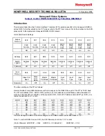
Page 94: ...84 84 84 84 ...

Page 95: ...85 85 85 85 ...

Page 96: ...86 86 86 86 ...

Page 97: ... 7 Once you have reached this point click ok and restart both the computer and the digital recorder 8 To access the DVR from the computer simply open Internet Explorer and in the address bar type http 192 168 1 3 ...

Page 98: ...2 Connection Procedure 1 The First step is to purchase or make a straight through cable We recommend purchasing one if you have never made a straight through cable Please remember you can not use a cross over network cable for this application 2 Once you have a straight through cable plug one end into the LAN port on the back of the recorder and the other into the high speed modem Cat 5 Straight T...

Page 99: ... and the default gateway of the internet service provider Note If you have a dynamic IP address you will need to enable and configure DDNS in the DVR s Network Menu Please refer to Chapter 3 7 6 and Chapter 13 for more information 5 Once you have reached this point click ok and restart both the computer and the digital recorder 6 To access the DVR from a computer simply open Internet Explorer and ...

Page 100: ...er r o or r L LA AN N C Co on nn ne ec ct ti io on n Straight Through Ethernet Cable Pin outs The Diagram below shows the pin configurations for a straight cable Diagram 10 3 Cat 5 Straight Through Cable Internet Hi speed modem DVR Router ...

Page 101: ... the jog dial from the previous chapter go to the Network Setting Menu 4 If you have a Linksys Router Assign an IP address of 192 168 001 050 to the DVR a Subnet mask of 255 255 255 000 and a default gateway of 192 168 001 001 If you have a D Link Router Assign an IP address of 192 168 000 050 to the DVR a Subnet mask of 255 255 255 000 and a default gateway of 192 168 000 001 If you have a pre ex...

Page 102: ...ovider blocks port 80 you may use a different port to access the DVR through the DVR s Network Menu Setup page 36 Note If you wish to have multiple users log into the DVR please open a range for the control and data ports on your router For example if you would only like 4 clients to connect to the DVR open 1600 1603 and 37260 37263 If you have a Dynamic IP address and have opened the ports go to ...

Page 103: ...plorer or Netscape Navigator and enter the Router s default IP address 192 168 1 1 in the Address Bar Then press Enter A password request page will appear Non Windows XP users will see a similar screen Leave the User Name field blank The first time you open the Web based Utility use the default password admin You can set a new password from the Administration tab s Management screen Click the OK b...

Page 104: ...ialized Internet applications Specialized Internet applications are any applications that use Internet access to perform functions such as videoconferencing or online gaming Some Internet applications may not require any forwarding To forward a port enter the information on each line for the criteria required Descriptions of each criteria are described here ...

Page 105: ...ication either TCP UDP or Both IP Address For each application enter the IP Address of the PC in this case the DVR running the specific application Enable Click the Enable checkbox to enable port forwarding for the relevant application Change these settings as described here and click the Save Settings button to apply your changes or Cancel Changes to cancel your changes Example DVR 80 to 80 Both ...

Page 106: ...ebsite FTP server or other server behind the Router Before you can use this feature you will need to create an account with a DDNS service provider such as www dyndns com DDNS Service From this pull down menu enter the DDNS service with which you have membership User Name Enter the User Name for your DDNS account Password Enter the Password for your DDNS account Host Name The DDNS name created thr...

Page 107: ...d on the model you are using some screens may be slightly different Please understand we do not support this product and will not give tech support on it If you need Technical support on this router you must call D Link This chapter is to only meant to offer basic assistance to the installer and end user Chapter 12 ...

Page 108: ... used to access the virtual service Private Port The port number of the service used by the Private IP computer Schedule The schedule of time when the virtual service will be enabled The schedule may be set to Always which will allow the particular service to always be enabled If it is set to Time select the time frame for the service to be enabled If the system time is outside of the scheduled ti...

Page 109: ...EDR Ports to open 80 1600 37260 37261 37262 37263 Note If your Internet service provider blocks port 80 and you are using a different port to access the DVR through the DVR s Network Menu Setup please open those specific ports in this section of the router 2 If your Internet Service Provider Blocks port 80 Simply do the following o Change the HTTP port from 80 to 8100 in the NETWORK MENU 3 To acce...

Page 110: ...tatic IP address 1 To setup Dynamic DNS simple go to Tools and the Misc At the bottom of the screen you will be able to enable DynDNS 2 Once you have enabled it enter the server address of you DDNS provider for example www dyndns com 3 Then enter the hostname you created with the DDNS provider Example company homeip net 4 Then enter the username and password you for your DDNS account ...

Page 111: ...nd end user 1 13 3 1 1 C Cr re ea at ti in ng g a a D DD DN NS S A Ac cc co ou un nt t 1 The first step is to open Internet Explorer and in the address bar type http www dyndns com 2 The next step is to register with dyndns com by clicking on Create Account 3 This is where you file out the information DynDNS requires You will then receive an email to confirm your account Once you confirm you will ...

Page 112: ...already be entered for you All you have to do is click add host and you are done registering DDNS 7 You may refer to the previous two chapters to set up DDNS within your router 8 To access the DVR from a computer simply open Internet Explorer and in the address bar type http The hostname you created example company homeip net ...

Page 113: ...appear on the screen similar to the one shown above 3 The default user name is admin and the password is 11111111 Remote User ID and Password can be found and changed in the Network Menu of the DVR 4 Click on the submit button and you will be logged into your recorder If the above error message pops up when you connect to DVR for viewing from internet you should change Internet Option of IE browse...

Page 114: ...104 104 104 104 Select Tools Internet Options Please refer to the above steps for changing Security Options to Low ...

Page 115: ... current mode The followings are a brief description for each of the icons 1 REV PLAY Reverse Video Playback 2 STOP Press this key to stop Playback and return to Live mode 3 PLAY Normal Video Playback 4 STEP BACKWARD Move one frame back while paused 5 PAUSE To pause the Video Playback display 6 STEP FORWARD Move one frame forward while paused 7 There are two methods of searching past video by Even...

Page 116: ...view 17 If you right click on a camera screen a drop down list of available cameras appears Click on the desired camera to display it in that view screen 18 There are 4 main functions of Remote Viewer SEARCH PTZ ARCHIVE and CONFIG SEARCH section allows you to search by event or by time PTZ section allows you to control PTZ cameras ARCHIVE section allows you to archive files or download DVRViewer C...

Page 117: ...e installed Keep pressing this button whenever you need to do audio broadcasting Release this button to stop transmitting audio to DVR 24 Relay Output Press the button to trigger relay output 25 OSD Press to show OSD information including camera name date time and event type Press again to hide them 1 14 4 1 1 S Se ea ar rc ch h 14 1 1 Search by TIME There are 3 ways to do search by time Press Pic...

Page 118: ...ter Month Day Hour Minute and second directly in display bar Press OK to start searching 14 1 2 Search by EVENT 1 Select Event Type from Alarm Motion and Vloss Note Please keep at least one event type checked 2 Select the Disk No from which you would like to search events 3 Press Update button to refresh the event list 4 All events of the selected type will be displaying along with Date Time event...

Page 119: ...w all the events of that page 6 Press Play button to playback the selected event 1 14 4 2 2 P PT TZ Z c co on nt tr ro ol l 1 Select the PTZ camera from drop down menu 2 Select Action Mode you want to use There are 4 options available Continuous Step x10 Step x5 and Step x1 3 Use Direction Arrows up down left right to move adjust the focus to your desired ...

Page 120: ...ou to define the preset point you want the camera to look at Press Set to confirm Clear to delete or Jump to jump to a specific point 8 Auto Pan is to define the speed of PTZ camera when moving horizontally Choose from Slower Slow Normal Fast to Faster Press Run to start or Stop to end 9 A B Point Scan allows you to set a tour between 2 points Move to the first point by using direction arrows and ...

Page 121: ...hive from 4 Start Select the start time of the archived video 5 End Select the end time of the archived video There are 3 ways to search either Start or End time to be archived Press first 1 Press on the M button to change the Month to be searched D for day h for hour m for minute and s for second The buttons on the left side are to decrease the value whereas those on the right side are to increas...

Page 122: ...lue 3 Enter Month Day Hour Minute and second directly in display bar 4 Press OK to select time 6 Press ARCHIVE button to start archiving An arv file will be saved 7 Press STOP button if you wish to cancel archiving 8 Check Display video if you wish to display what you are archiving on the screen while archiving file at same time ...

Page 123: ...113 113 113 113 In order to play the archived EDR MPEG4 Files arv you will need to download viewer 1 Press Download DVRViewer button 2 Select Run or Save the file ...

Page 124: ...follows i Load File to load the archived EDR MPEG4 Files arv ii Stop to stop playing video iii Play to play video iv Step step backward after pausing v Pause to pause playing vi Step step forward after pausing vii Capture to capture the current image as jpg file viii Save to Avi to save the archived EDR MPEG4 File as AVI file ...

Page 125: ...corded please select Audio ON so that the audio can be transferred to AVI file Otherwise select Audio OFF Note If you are unable to play AVI file downloaded from DVRViewer your PC may require a video codec The codec can be found at the following URL http www divx com divx windows codec If you continue to have problems or are unable to download this file you can also try http www cole2k net display...

Page 126: ...e the DVR s settings Click on each option to go to the settings for that page When you finish making changes on a screen press Apply to save the settings Press Reset to display the DVR s current menu settings The settings you make remotely in this page are virtually the same as the way you set up the DVR itself except for as noted in the following pages ...

Page 127: ...w 2 Click to decrease Year value to increase Year value 3 Click to decrease Month value to increase Month value 4 Click on the selected date directly 5 Click on the Hour Minute Seconds to change Time value Up arrow for increasing and Down arrow for decreasing the value This is also used to change between Am and Pm 6 Finally click Apply to confirm setting ...

Page 128: ...118 118 118 118 CAMERA setup menu RECORD setup menu ALARM setup menu ...

Page 129: ...disabled for motion green squares are enabled 2 Click and hold the mouse to begin selecting squares in the motion grid 3 Drag the mouse to highlight the desired area 4 The selected area will switch to the opposite color 5 Click Apply to save the changes VIDEO LOSS setup menu ...

Page 130: ... Configuration Settings can not be changed remotely These must be changed in the DVR s Network Menu NETWORK 2 setup menu After saving changes to the account password or level the changes will take effect the next time you log in to the network viewer ...

Page 131: ...121 121 121 121 SCHEDULE setup menu CONTROL setup menu ...

Page 132: ...o open the menu or make changes at the DVR while this process is happening 4 When the update is complete the DVR will reboot automatically 5 Once Load System has finished the system s software will be updated You will need to refresh the network viewer for the changes to take effect Load Save Configuration 1 Clicking Save will open a Save File window 2 Select the folder you wish to save the config...

Page 133: ...123 123 123 123 AppendixA RemoteControl Appendix A ...

Page 134: ...124 124 124 124 AppendixB AlarmBoardConfiguration EDVR16D1 F1 EDVR16D2 F2 EDVR9D1 F1 EDVR4D1 F1 models Appendix B ...

Page 135: ...M_NO2 25 ALM_COM2 26 ALM_NC3 27 ALM_NO3 28 ALM_COM3 29 ALM_NC4 30 ALM_NO4 31 ALM_COM4 32 ALMRST 33 REC_IN 34 SPARE_IN 35 DISK_FULL 36 SPARE_OUT 37 GND HOST PIN NAME 1 GND 2 ALMIN 1 3 ALMIN 2 4 ALMIN 3 5 ALMIN 4 6 ALMIN 5 7 GND 8 ALMIN 6 9 ALMIN 7 10 ALMIN 8 11 ALMIN 9 12 ALMIN 10 13 GND 14 ALMIN 11 15 ALMIN 12 16 ALMIN 13 17 ALMIN 14 18 ALMIN 15 19 ALMIN 16 20 GND 21 GND 22 ALM_NC1 23 ALM_NO1 24 A...

Page 136: ...re more of below listed events appears a HDD full If overwrite mode in RECORD menu is set to STOP b No HDD c Over temperature HDD d Power Loss e Cooler fan fault f Video Loss g Record off Output level HIGH 5 V DC System okay Open state System error SPARE_IN N O Control input for playback function playback is active as long contact is closed ...

Page 137: ...127 127 127 127 AppendixC RJ45 RS485 PinAssignment Appendix C ...

Page 138: ... however if there is constant change between the images it will use the size for a complex image The times given in the following tables show the absolute maximum and minimum for these sizes and should only be used as a reference Terms of Use The HDD size required in your DVR may vary from this calculated test result under some conditions Total storage capacity may vary depending on complexity of ...

Page 139: ... 443 79 589 71 352 44 466 70 288 87 4 2159 1408 04 2061 89 1267 23 1710 45 1038 34 1463 84 887 58 1179 42 704 88 933 39 577 74 PAL Unit Hour PICTURE QUALITY LOWER LOW BASIC STANDARD HIGH SUPERIOR simple complex simple complex simple complex simple complex simple complex simple complex Recording Speed IPS 8 04 12 33 8 42 13 7 10 15 16 72 11 86 19 56 14 72 24 63 18 6 30 05 25 345 5 225 29 329 90 202...

Page 140: ...67 343 65 211 21 285 08 173 06 243 97 147 93 196 57 117 48 155 57 96 29 16 539 84 352 01 515 47 316 81 427 61 259 59 365 96 221 90 294 86 176 22 233 35 144 44 PAL Unit Hour PICTURE QUALITY LOWER LOW BASIC STANDARD HIGH SUPERIOR simple complex simple complex simple complex simple complex simple complex simple complex Recording Speed IPS 8 04 12 33 8 42 13 7 10 15 16 72 11 86 19 56 14 72 24 63 18 6 ...

Page 141: ...257 74 158 40 213 81 129 79 182 98 110 95 147 43 88 11 116 67 72 22 16 539 84 352 01 515 47 316 81 427 61 259 59 365 96 221 90 294 86 176 22 233 35 144 44 PAL Unit Hour PICTURE QUALITY LOWER LOW BASIC STANDARD HIGH SUPERIOR simple complex simple complex simple complex simple complex simple complex simple complex Recording Speed IPS 8 04 12 33 8 42 13 7 10 15 16 72 11 86 19 56 14 72 24 63 18 6 30 0...

Page 142: ...132 132 132 132 APPENDIXE InstallationStepsOfNEROInCDSoftware 1 Insert Nero InCD installation CD and select Nero 7 Essentials 2 Click Next when Nero 7 Essentials installation wizard shows up Appendix E ...

Page 143: ...133 133 133 133 3 Please read the license agreement and press Next 4 Please enter customer information and press Next ...

Page 144: ...134 134 134 134 5 Select Custom for Setup Type This option will allow you to choose the program features that you want to install 6 Select the language you want to be supported ...

Page 145: ...135 135 135 135 7 Select InCD as the destination folder for Nero 7 Essentials 8 Select the program features you want to install ...

Page 146: ...es will be installed on the local hard drive 10 At the right bottom part of wizard it indicates the information about the hard drive capacity it requires for installation and feature As well as the number of subfeatures selected and the hard drive capacity required for subfeatures ...

Page 147: ...lick Install to begin the installation If you wish to review or change any of your installation settings click Back Or click Cancel to exit the wizard 12 Please wait while the installation wizard installs Nero 7 Essentials ...

Page 148: ...138 138 138 138 13 Please select file associations and other options 14 Once the installation is completed press Finish to exit the installation Wizard ...

Page 149: ...tart your system for the configuration changes made to Nero 7 Essentials to take effect Click Yes to restart immediately or No to start manually later 16 Information about the selected drive indicates device information device capabilities and disc status ...

Page 150: ...140 140 140 140 17 Format disc prepare your disc for file writing ...

Page 151: ...ta bit RS232 49 RS485 49 Data port 38 Display 4 Duration Alarm 29 Motion 32 Video Loss 35 Dynamic DNS 99 Event Camera 24 Event Search menu 66 F icon 11 FQDN 43 Gateway 37 HTTP port 37 Image 69 Install Covert 22 IP Address 37 LH 67 Load Save Configuration 56 Log Alarm 29 Motion 32 Video Loss 34 M icon 10 MAC ADDR 38 Main Mon Alarm 30 Motion 32 Mode 5 Motion Delay 32 Motion Recording Only 62 Normal ...

Page 152: ...10 Search 65 Select 10 Sender Email Address 40 Sensitivity 31 Server 1 2 3 39 Sequence 22 Set temperature 52 SMTP 40 Stop bit RS232 48 RS485 49 Subnet mask 37 T icon 11 Time server 19 Time stamp 26 Time synchronize 19 Time update by 20 Time zone 20 TP 1 8 23 TN 67 Unique ID 39 User email 40 User DDNS 43 Upgrade firmware 75 V icon 10 Viewer 69 Watermark 26 Zoom 73 icon 10 ...

Page 153: ...verify the recorder is getting the correct amount of power There is no display coming from one of the channels on the DVR The first step is to verify is the problem coming from the recorder or the camera Simply take a working camera and plug it into the port that seems to not be working If you see a picture this means the problem is coming from the camera I cannot connect to the recorder via the i...

Page 154: ...chnology DDNS it allows you to overcome this problem DDNS lets you assign a fixed host and domain name to a dynamic Internet IP address It is useful when you are hosting your own DVR website FTP server or other server behind the Router Before using this feature you need to sign up for DDNS service at www dyndns org or www tzo com Preferred routers Linksys BEFSR41 V3 or DLINK DI624 or any router th...

Page 155: ...m P N MDVRG0011A_Ver D Your EverFocus product is designed and manufactured with high quality materials and components which can be recycled and reused This symbol means that electrical and electronic equipment at their end of life should be disposed of separately from your household waste Please dispose of this equipment at your local community waste collection recycling centre In the European Uni...

Reviews: