background image


Bedienungsanleitung
User manual

LED
KLS--170

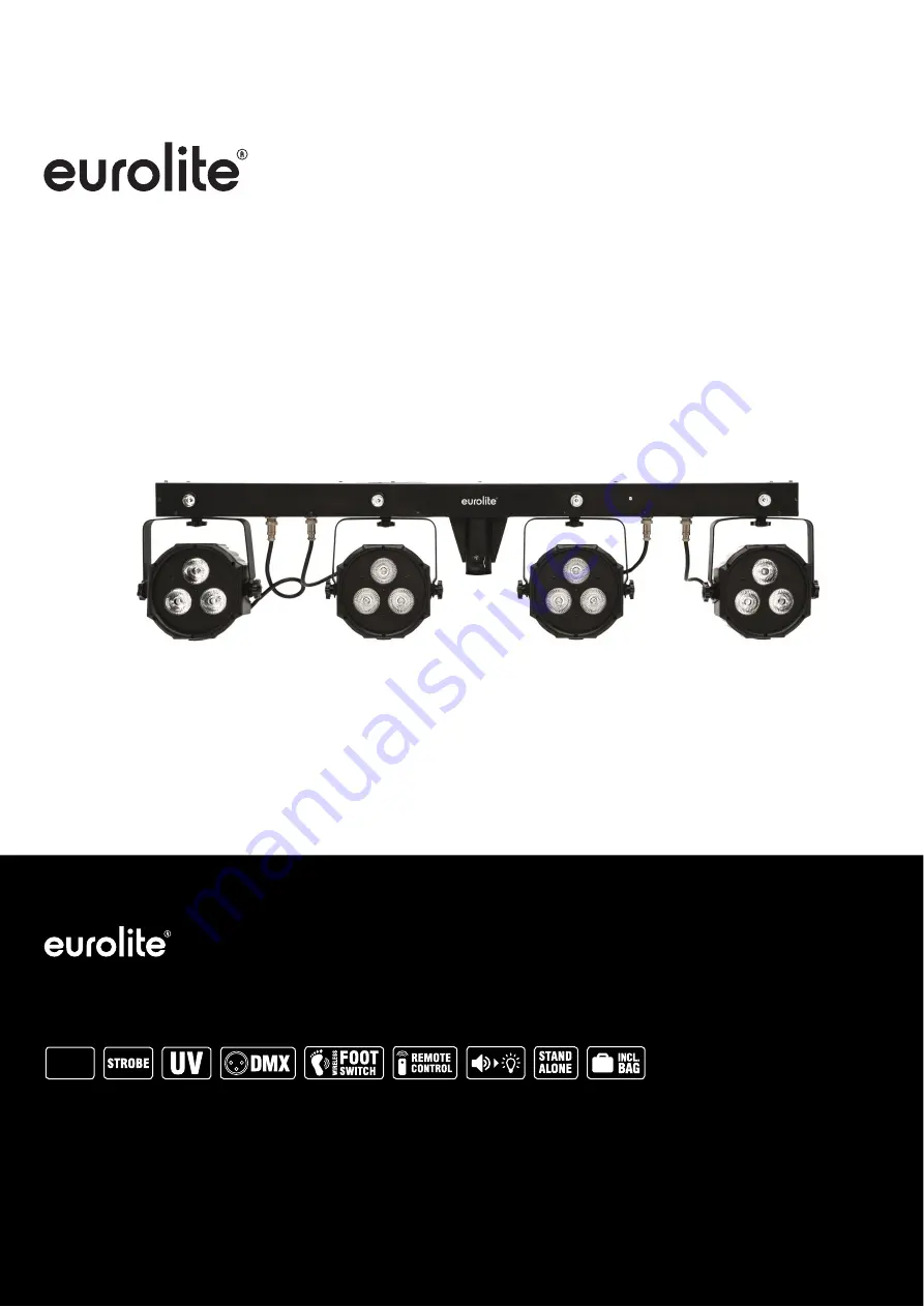
Compact light set

Compact light set

Bar mit 4 RGB-Spots, kaltweißen + UV-Strobe-LEDs, Fußcontroller, Tasche
Bar with 4 RGB spots, cold white + UV strobe LEDs, foot switch and bag

No. 42109620

www.eurolite.de

RGB


Summary of Contents for LED KLS-170

Page 1: ...er manual LED KLS 170 Compact light set Compact light set Bar mit 4 RGB Spots kaltweißen UV Strobe LEDs Fußcontroller Tasche Bar with 4 RGB spots cold white UV strobe LEDs foot switch and bag No 42109620 www eurolite de RGB ...

Page 2: ... INSTRUCTIONS 18 DESCRIPTION OF THE DEVICE 20 INSTALLATION 21 Mounting on a stand 21 Overhead rigging 21 CONNECTIONS 22 DMX512 control 22 Connection to the mains 22 Power supply of further devices 22 OPERATION 23 Stand alone mode 24 Interconnecting several devices master slave operation 25 Operation with the foot switch 25 Operation with the IR remote control 26 DMX operation 27 CLEANING AND MAINT...

Page 3: ...tzte Version der Anleitung im Internet herunter laden EINFÜHRUNG Wir freuen uns dass Sie sich für eines unserer Produkte entschieden haben Wenn Sie nachfolgende Hinweise beachten sind wir sicher dass Sie lange Zeit Freude an Ihrem Kauf haben werden Produktmerkmale 2 in1 DMX Lichtanlage mit vier superflachen LED Spots und Strobe LEDs in Weiß und UV Absolutes Leichtgewicht bestens geeignet für mobil...

Page 4: ...deren Spannung und Frequenz mit dem Typenschild des Geräts genau übereinstimmt und die über einen Fehlerstromschutzschalter FI abgesichert ist Wenn der Netzstecker mit einem Schutzkontakt ausgestattet ist muss er an eine Steckdose mit Schutzleiter angeschlossen werden Deaktivieren Sie niemals den Schutzleiter eines Netzkabels Nichtbeachtung kann zu Schäden am Gerät und zu Verletzungen des Benutzer...

Page 5: ...ondern beauftragen Sie einen professionellen Installateur Unsachgemäße Installationen können zu Verletzungen und oder zur Beschädigung von Eigentum führen Der Hersteller haftet nicht für Schäden die durch unsachgemäße Installation und unzureichende Sicher heitsvorkehrungen verursacht werden Bei einer Montage über Kopf ist das Gerät immer durch eine zweite Befestigung z B Fangseil oder Fangnetz zu ...

Page 6: ...fon für Musiksteuerung Infrarotempfänger für die Fernbedienung Rückseite DMX Ausgang Empfindlichkeitsregler für das Mikrofon DMX Eingang Display und Bedientasten Netzdurchschleifausgang Infrarotempfänger für die Fernbedienung Netzanschluss mit Sicherungshalter Unterseite Montagepunkte für die LED Spots Anschlüsse für die LED Spots ...

Page 7: ...lb des Handbereichs von Personen Bezogen auf den jeweiligen Standort sind alle notwendigen Maßnahmen gegen Verschieben und zur Sicherstellung der Standsicherheit zu schaffen auch unter Brandbedingungen Überkopfmontage WARNUNG Verletzungsgefahr durch Herabfallen Über Kopf installierte Geräte können beim Herabstürzen erhebliche Verletzungen verursachen Stellen Sie sicher dass das Gerät sicher instal...

Page 8: ...m mögliche Korrosion Verformung und Lockerung zu vermeiden ANSCHLÜSSE DMX512 Ansteuerung Für die Ansteuerung des Geräts per DMX512 ist eine Datenverbindung notwendig Das Gerät verfügt dazu über 3 polige XLR Anschlüsse 1 Verbinden Sie den Ausgang Ihres Controllers mit dem DMX Eingang DMX IN des Geräts über ein DMX Kabel 2 Verbinden Sie den DMX Ausgang DMX OUT des Geräts mit dem DMX Eingang des näch...

Page 9: ...ert den Einstellvorgang eines Menüpunkts oder speichert eine Einstellung UP Ruft den nächsten Menüpunkt auf oder erhöht Werte beim Einstellvorgang DOWN Ruft den vorhergehenden Menüpunkt auf oder verringert Werte beim Einstellvorgang Menüstruktur Modus Anzeige Funktion Aut Automatikbetrieb Spots AutP AP01 AP17 Showprogramm 1 17 S 01 S 99 Ablaufgeschwindigkeit langsam schnell Strobe LEDs AutF AF01 A...

Page 10: ...ste ENTER Das Menü für die Ablaufgeschwindigkeit wird aufgerufen 4 Stellen Sie mit und die Ablaufgeschwindigkeit des Programms von S 01 langsam bis S 99 schnell ein Bestätigen Sie mit ENTER Musiksteuerung Durch das integrierte Mikrofon lassen sich die integrierten Showprogramme im Rhythmus der Musik bei deutlichem Bassschlag optimal mit dem Gerät wiedergeben 1 Drücken Sie die Taste MENU so oft bis...

Page 11: ...ist jetzt als Master definiert 4 Wählen Sie das gewünschte Showprogramm Automatikbetrieb oder mit Musiksteuerung Die zusammen geschalteten Lichtleisten arbeiten nun synchron Fernbedienung mit dem Fußschalter Das Lichtset lässt sich mit dem optionalen Fußschalter über eine Distanz von bis zu 30 Metern Sichtlinie fernsteuern Der Fußschalter funktioniert nur im Standalone Betrieb er kann nicht im DMX...

Page 12: ...der SP01 SP12 für die LED Spots Showprogramm AF01 AF10 oder SF01 SF10 für die Strobe LEDs Umschaltung Automatikbetrieb Musiksteuerung Pause Farbwahl Modus CoLo R G RG B RB GB RGB Ablaufgeschwindigkeit der Showprogramme im Automatikbetrieb Batterie Die Fernbedienung wird mit eingesetzter Batterie geliefert Damit die Batterie während der Lagerung nicht entladen werden kann befindet sich eine Isolier...

Page 13: ...ktionen im DMX Betrieb 3 Kanal Modus Kanal Wert Funktion Blackout Automatikbetrieb und Musiksteuerung 1 000 009 Blackout 010 050 Automatikbetrieb Spots 051 090 Automatikbetrieb Strobe LEDs 091 130 Automatikbetrieb Spots und Strobe LEDs 131 170 Musiksteuerung Spots 171 210 Musiksteuerung Strobe LEDs 211 255 Musiksteuerung Spots und Strobe LEDs Programmwahl für Automatikbetrieb und Musiksteuerung 2 ...

Page 14: ... Modus Kanal Wert Funktion Steuerung Spots und Strobe LEDs 1 000 255 Helligkeit Rot 0 100 2 000 255 Helligkeit Grün 0 100 3 000 255 Helligkeit Blau 0 100 4 000 191 Masterdimmer 0 100 192 200 Musikgesteuerter Strobe 201 249 Strobe Effekt langsam schnell 250 255 Masterdimmer 100 5 000 127 Weiße LEDs an 128 133 UV LEDs an 6 000 249 Weißer Strobe Effekt oder UV Strobe Effekt 250 255 Weiße LEDs oder UV...

Page 15: ...änden von Verunreinigungen wie Staub usw gereinigt werden Insbesondere die Linsen sollten sauber sein damit das Licht mit maximaler Helligkeit abgestrahlt werden kann 1 Trennen Sie das Gerät vom Netz und lassen Sie es abkühlen bevor Sie mit der Reinigung beginnen 2 Reinigen Sie die Oberflächen mit einem fusselfreien angefeuchteten Tuch Verwenden Sie auf keinen Fall Alkohol oder irgendwelche Lösung...

Page 16: ...g von Batterien und Akkus leisten Sie einen wichtigen Beitrag zum Schutz unserer Umwelt TECHNISCHE DATEN Spannungsversorgung 100 240 V AC 50 60 Hz Gesamtanschlusswert 90 W Sicherung T1 6A 250V LEDs Spot 12 x 9 W RGB 3in1 LEDs Strobe 4 x 2 W weiß UV 2in1 Abstrahlwinkel 13 Spot 8 Strobe Blitzrate 0 30 Hz DMX Steuerkanäle 3 6 16 25 DMX512 Anschluss 3 pol XLR TV Zapfen Ø 28 mm Musiksteuerung über eing...

Page 17: ...he user manual from the Internet INTRODUCTION Thank you for having chosen one of our products If you follow the instructions given in this manual we are sure that you will enjoy this device for a long period of time Product features 2 in 1 DMX light set with four slim line LED spots and strobe LEDs in white and UV Ultra light ideally suited for mobile use Crossbar with integrated DMX control unit ...

Page 18: ... could possibly injure the user The mains outlet must be easily accessible so that you can unplug the device quickly if need be Never touch the mains plug with wet or damp hands There is the risk of potentially fatal electric shock The mains cable must not be bent or squeezed Keep it away from hot surfaces or sharp edges Never pull the mains cable to disconnect the mains plug from the mains outlet...

Page 19: ...ecure the device with a secondary safety attachment such as a safety bond or safety net Make sure that the area below the installation place is blocked when rigging derigging or servicing the device For commercial use the country specific accident prevention regulations of the government safety organization for electrical facilities must be complied with at all times Caution material damage This d...

Page 20: ...phone for sound controlled operation Infrared sensor for the remote control Rear panel DMX output Sensitivity control for the microphone DMX input Display and operating buttons Power feed through output Infrared sensor for the remote control Power input with fuse holder Bottom Mounting locations for the LED spots Connectors for the LED spots ...

Page 21: ... and out of the reach of people Depending upon the individual installation spot all necessary measures against movement and for securing the standing safety have to be created also in case of fire Overhead rigging WARNING Risk of injury caused by falling objects Devices in overhead installations may cause severe injuries when crashing down Make sure that the device is installed securely and cannot...

Page 22: ...DMX512 data link is required in order to control the device via DMX The device provides 3 pin XLR connectors for DMX connection 1 Connect the output of your DMX controller to the DMX input DMX IN of the light set with a DMX cable 2 Connect the DMX output DMX OUT of the light set to the DMX input of the next unit in the chain Always connect one output to the input of the next unit until all units a...

Page 23: ...program 1 11 S 01 S 99 Running speed slow fast Spots and strobe LEDs AutM AM01 AM03 Show program 1 3 S 01 S 99 Running speed slow fast Sou Sound control Spots SouP SP01 SP12 Show program 1 12 Strobe LEDs SouF SF01 SF11 Show program 1 11 Spots and strobe LEDs SouM SM01 SM03 Show program 1 3 CoL Color mode Spots and strobe LEDs CoLo R 000 R 255 Red 0 255 G 000 G 255 Green 0 255 B 000 B 255 Blue 0 25...

Page 24: ...rm with ENTER Sound control Via the integrated microphone the unit can perfectly reproduce the show programs to the rhythm of the music sufficient bass provided 1 Press the MENU button so many times until Sou for sound control is indicated in the display Confirm with the ENTER button 2 Use the and buttons to select the desired program mode SouP spots SouF strobe LEDs or SouM for a combination of a...

Page 25: ...tons Confirm with ENTER 3 Use and to select the setting ON Thus the unit is set to master 4 Select the desired show program automatic mode or sound controlled mode The interconnected light sets will now operate in sync Operation with the foot switch The optional wireless foot switch allows convenient control of the light set over a distance of up to 30 meters line of sight The foot switch will onl...

Page 26: ...program AP01 AP17 or SP01 SP12 for the LED spots Show program AF01 AF10 or SF01 SF10 for the strobe LEDs Switching between automatic mode sound controlled mode Pause Color selection CoLo mode R G RG B RB GB RGB Running speed of the show programs in automatic mode Battery The remote control is supplied with a battery inserted An insulating foil between the battery and the battery contacts prevents ...

Page 27: ...de 3 channel mode Channel Value Function Blackout automatic mode and sound controlled mode 1 000 009 Blackout 010 050 Automatic mode spots 051 090 Automatic mode strobe LEDs 091 130 Automatic mode spots and strobe LEDs 131 170 Sound control spots 171 210 Sound control strobe LEDs 211 255 Sound control spots and strobe LEDs Program selection for automatic mode and sound controlled mode 000 255 Auto...

Page 28: ...t 6 channel mode Channel Value Function Spots and strobe LEDs 1 000 255 Brightness red 0 100 2 000 255 Brightness green 0 100 3 000 255 Brightness blue 0 100 4 000 191 Master dimmer 0 100 192 200 Sound controlled strobe effect 201 249 Strobe effect slow fast 250 255 Master dimmer 100 5 000 127 White LEDs on 128 133 UV LEDs on 6 000 249 Master strobe effect or UV strobe effect 250 255 White LEDs or...

Page 29: ...aned periodically to remove contaminants such as dust etc The lenses in particular should be clean to ensure that light will be emitted at maximum brightness 1 Disconnect the device from power and allow it to cool before cleaning 2 Clean the surface with a soft lint free and moistened cloth Never use alcohol or solvents as these may damage the surface Make sure that no liquids can enter the device...

Page 30: ...eries correctly you contribute to the protection of the environment TECHNICAL SPECIFICATIONS Power supply 100 240 V AC 50 60 Hz Power consumption 90 W Fuse T1 6A 250V LEDs spots 12 x 9 W RGB 3in1 LEDs strobe 4 x 2 W white UV 2in1 Beam angle 13 spots 8 strobe Flash rate 0 30 Hz DMX channels 3 6 16 25 DMX512 connection 3 pin XLR TV spigot Ø 28 mm Sound control via built in microphone Dimensions L x ...

Page 31: ......

Page 32: ...Eurolite is a brand of Steinigke Showtechnic GmbH Andreas Bauer Str 5 97297 Waldbüttelbrunn Germany D00121009 Version 1 1 Publ 24 06 2019 ...

Reviews: